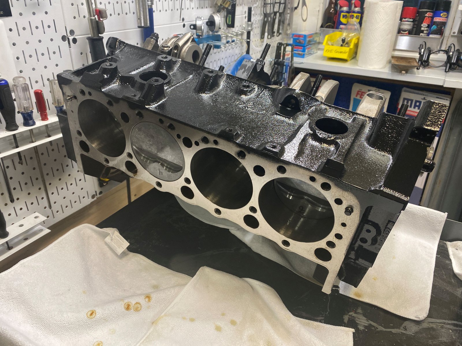
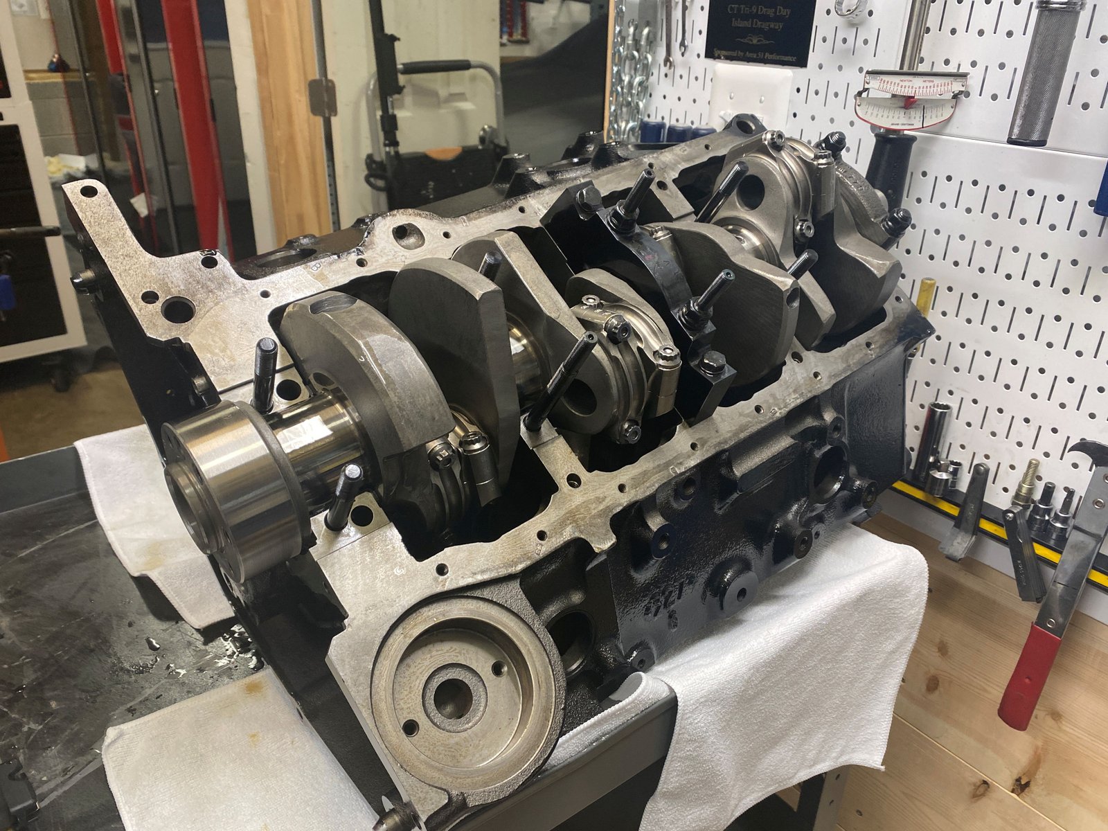
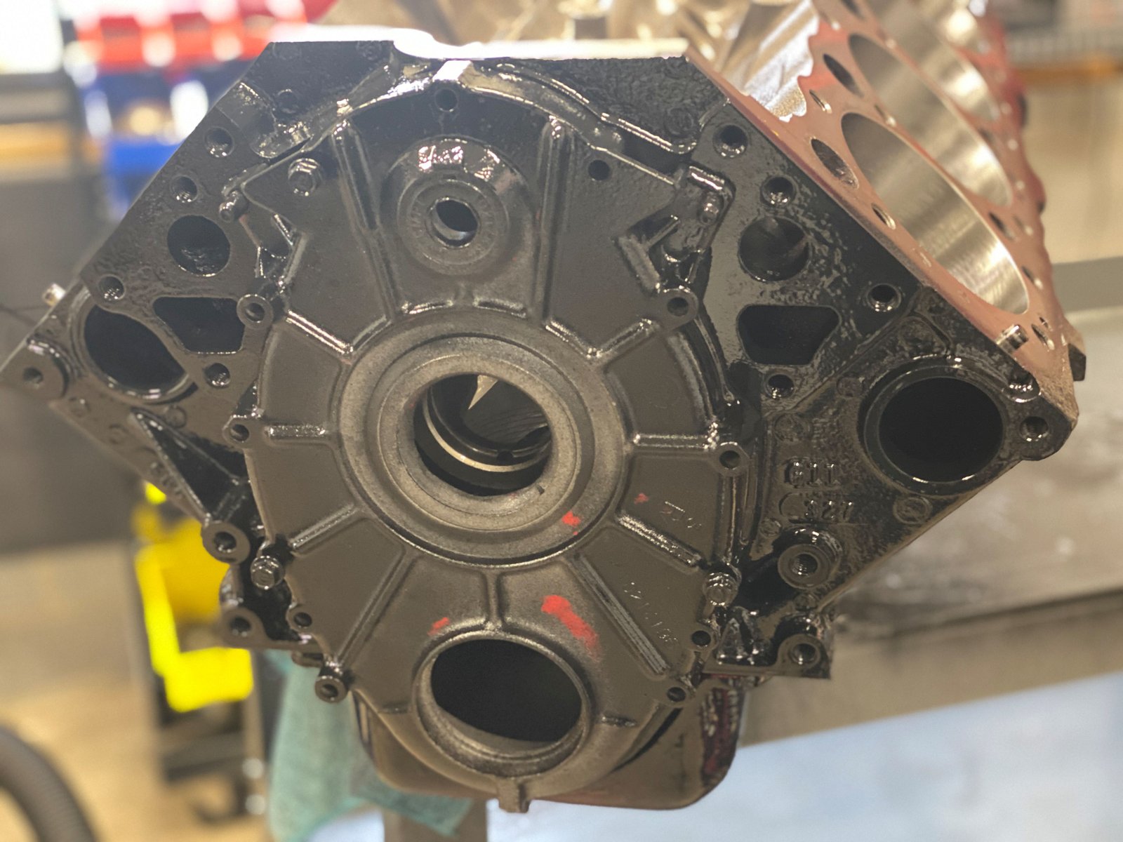
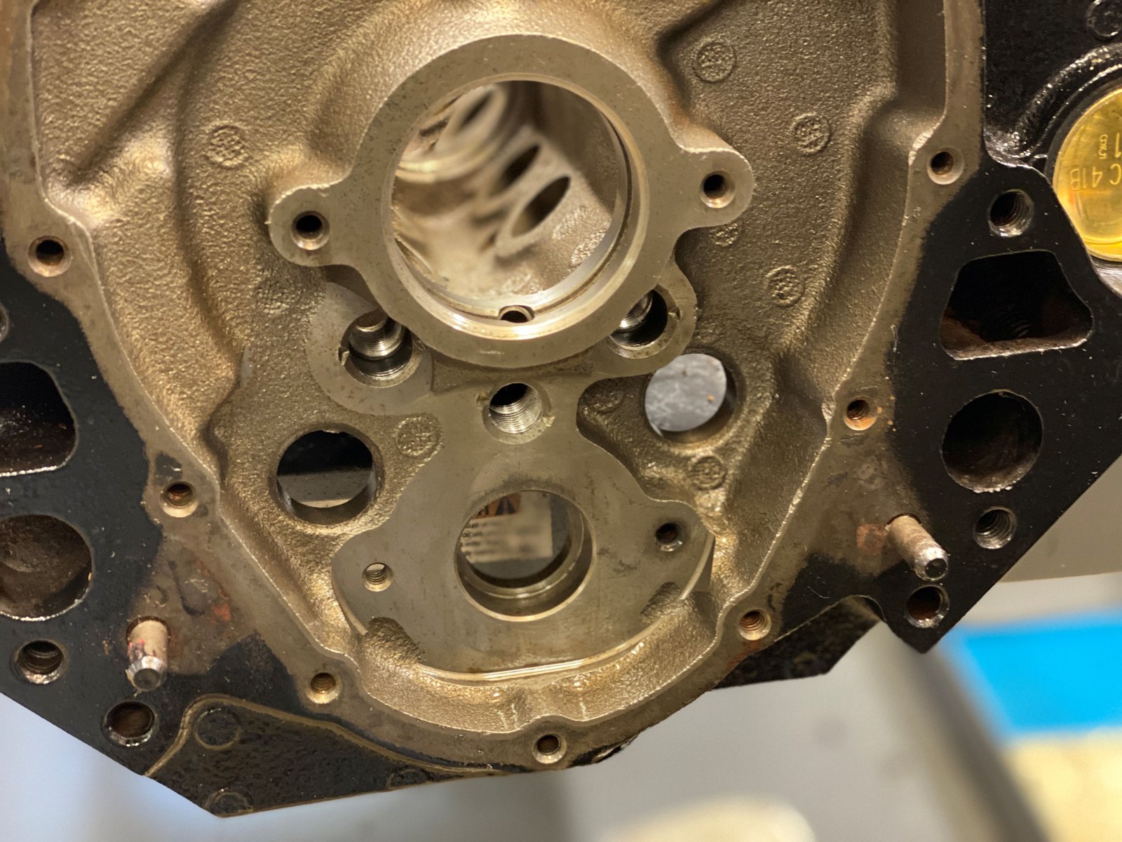
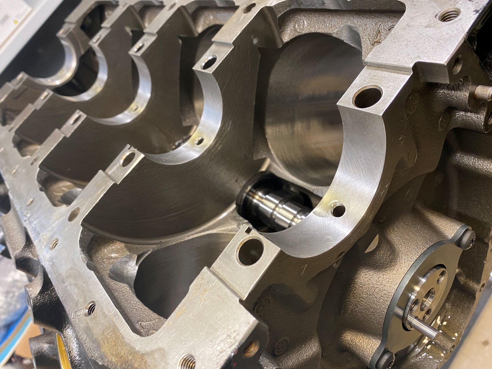
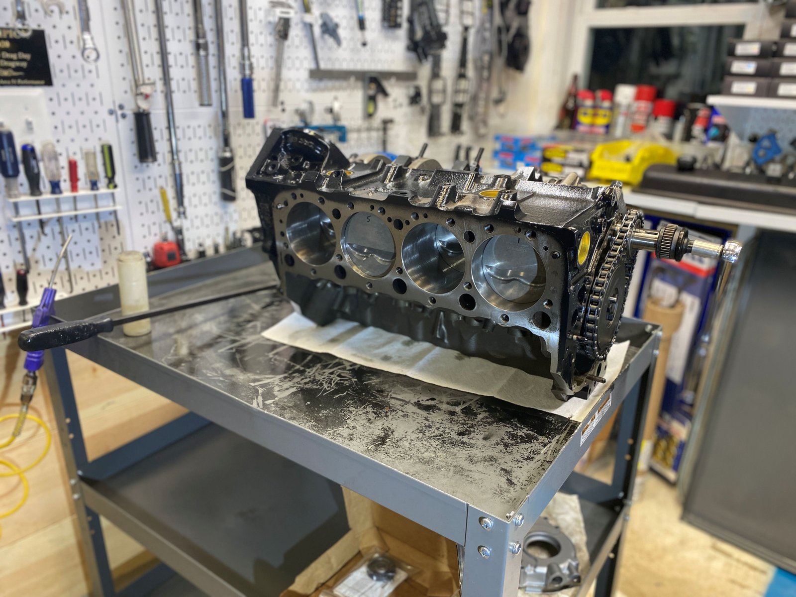
Starting the build off at the "beginning". The
block is fully machined but there are numerous things that I do to
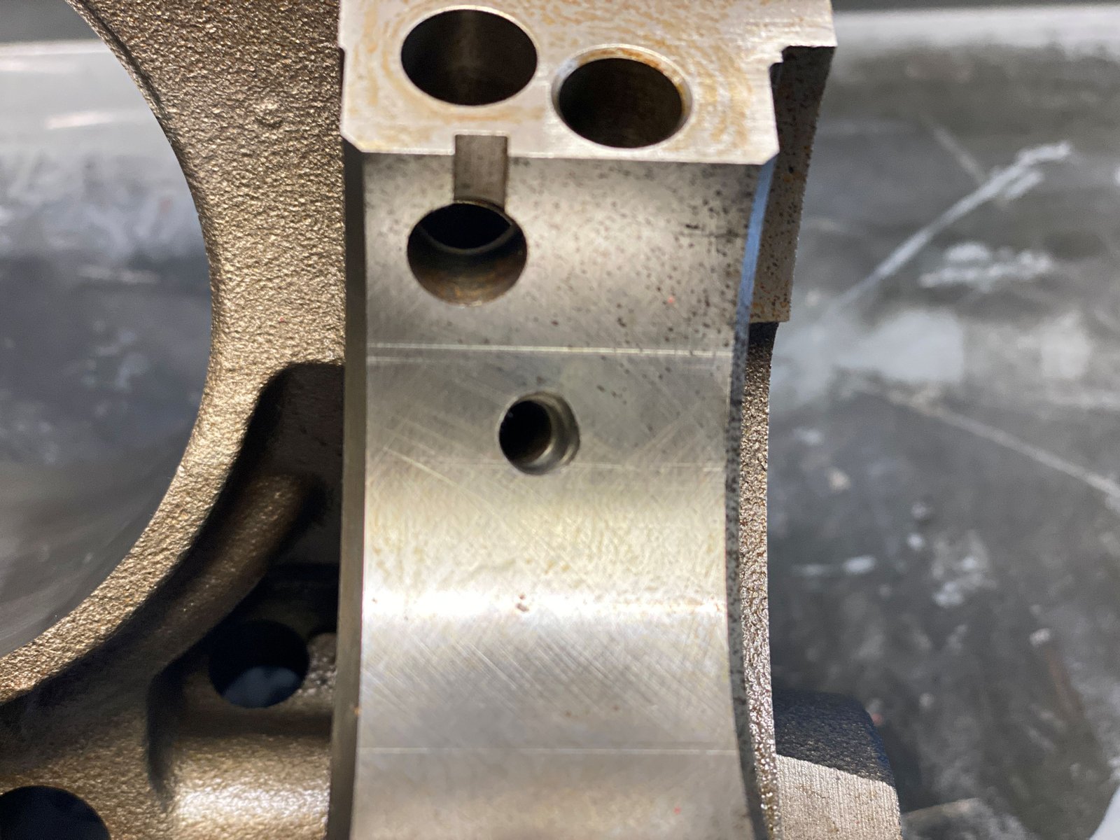
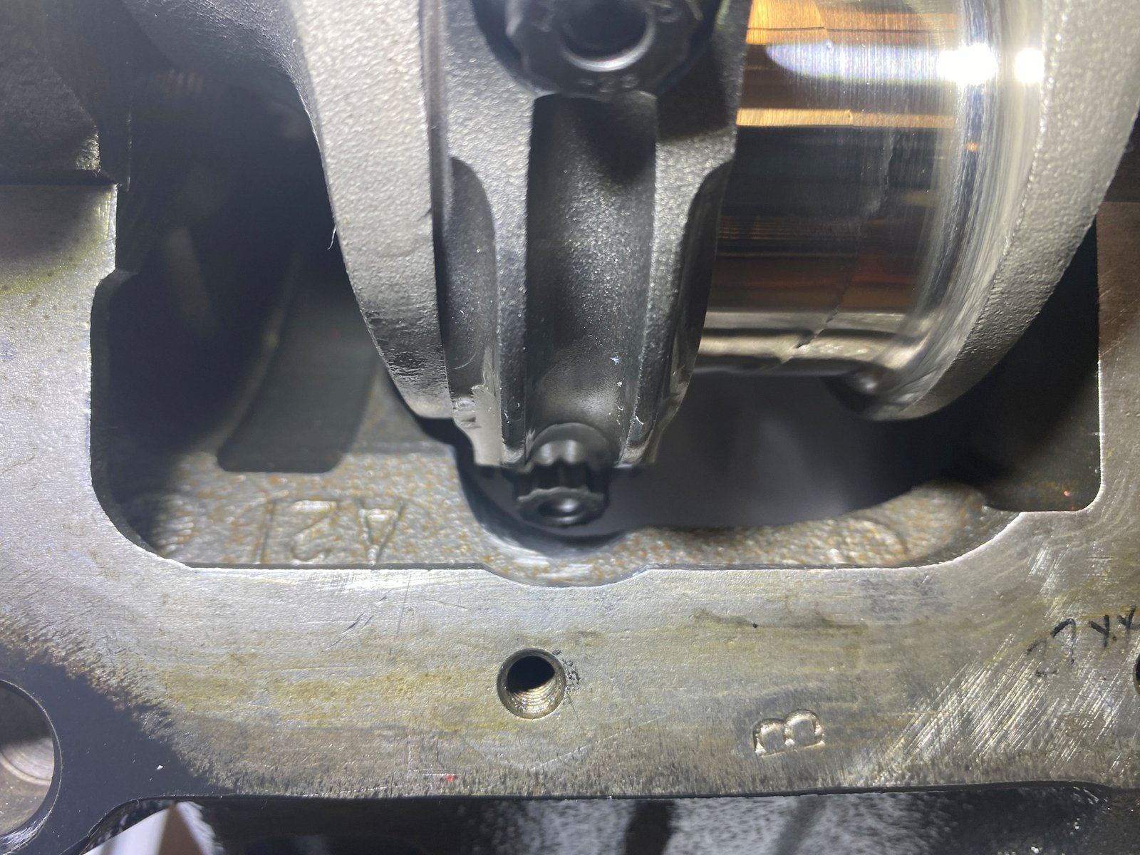
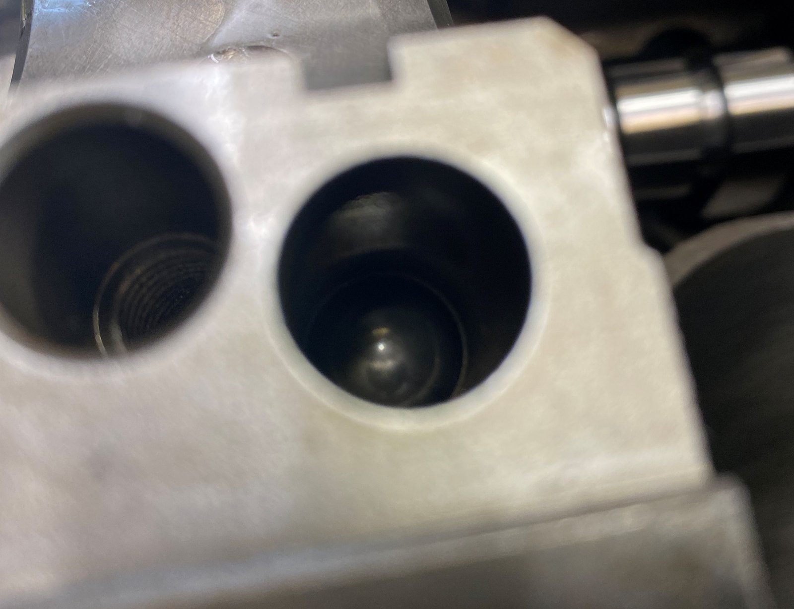
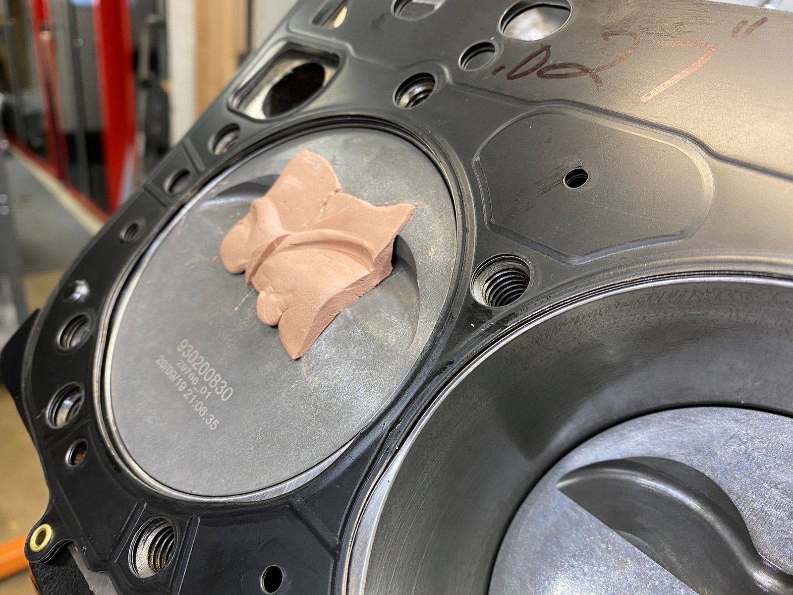
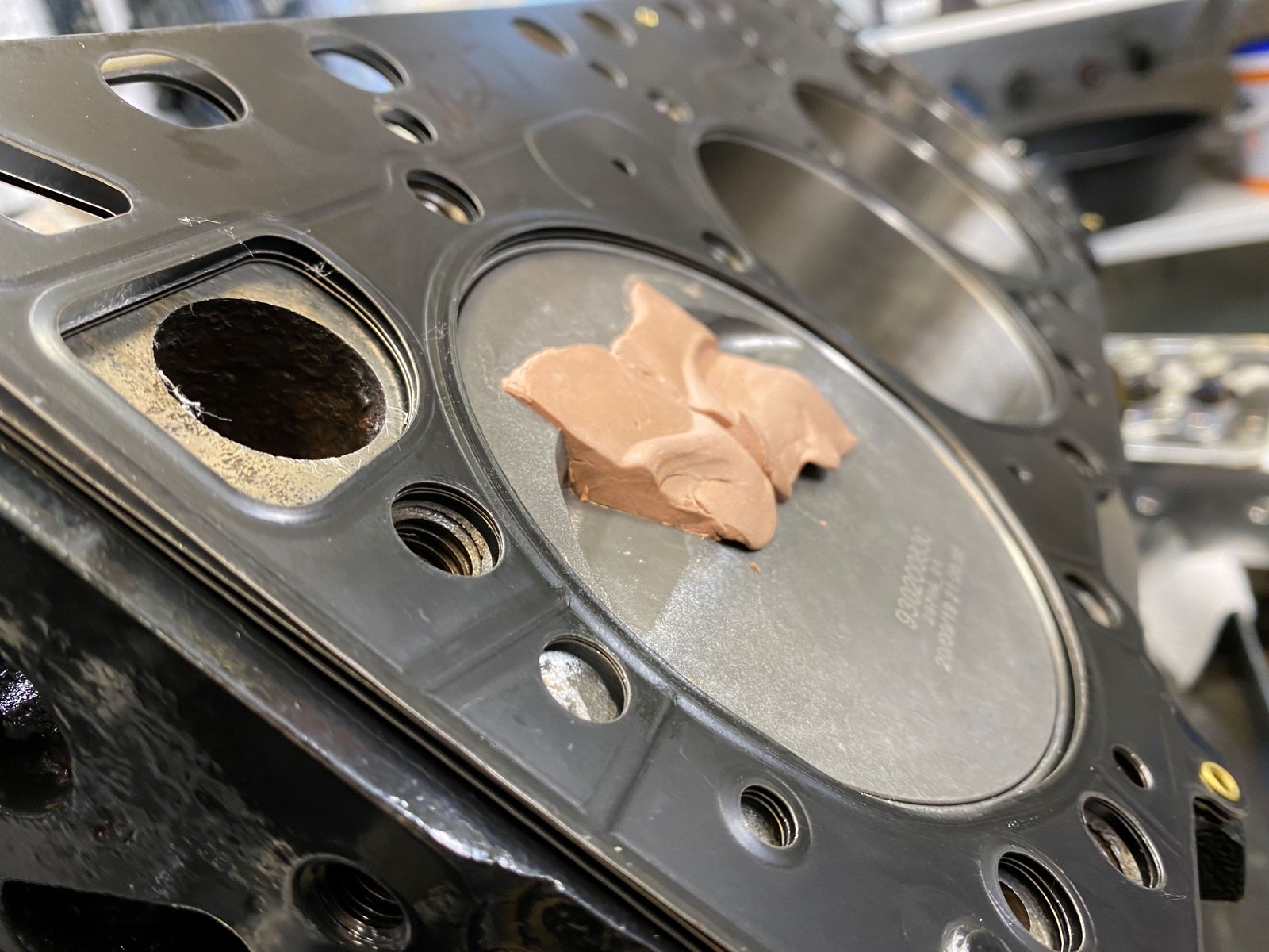
it prior to assembly. I match this oil galley hole to the
bearing....
|

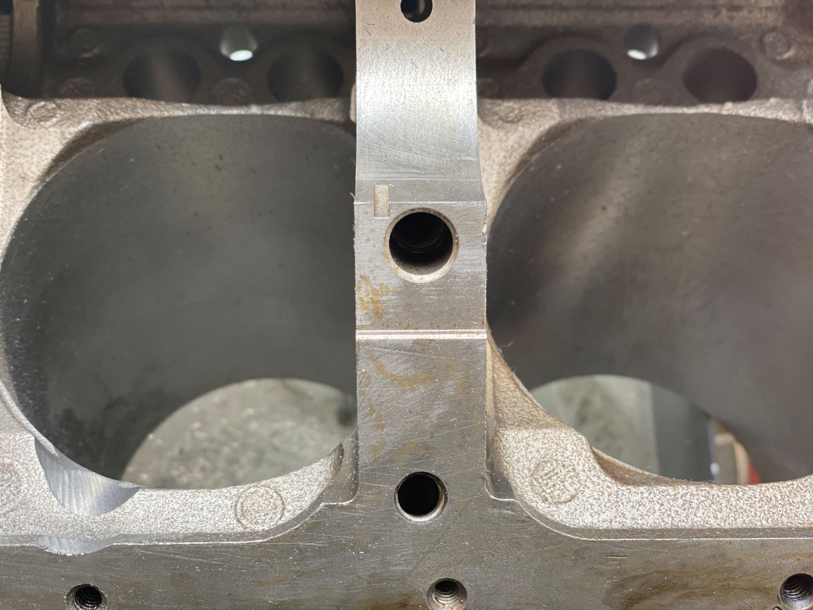
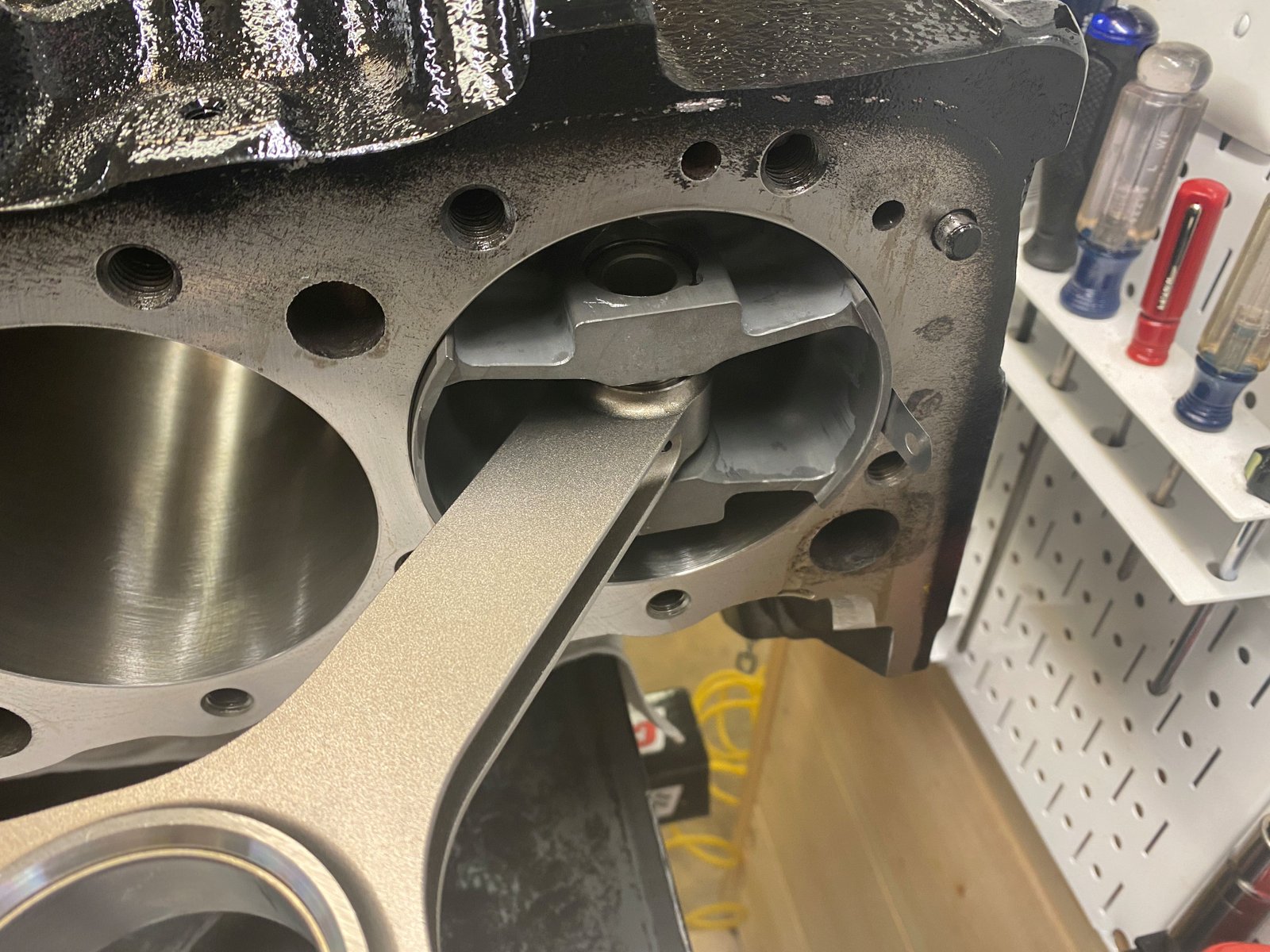
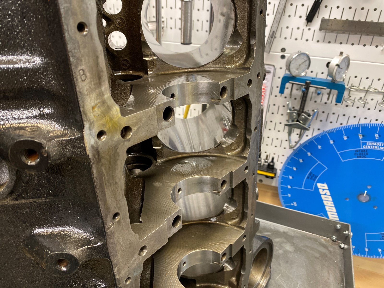
.....I clearance the bottom of the bores for rod-stroke.
The left bore is clearanced and the right bore is stock. |

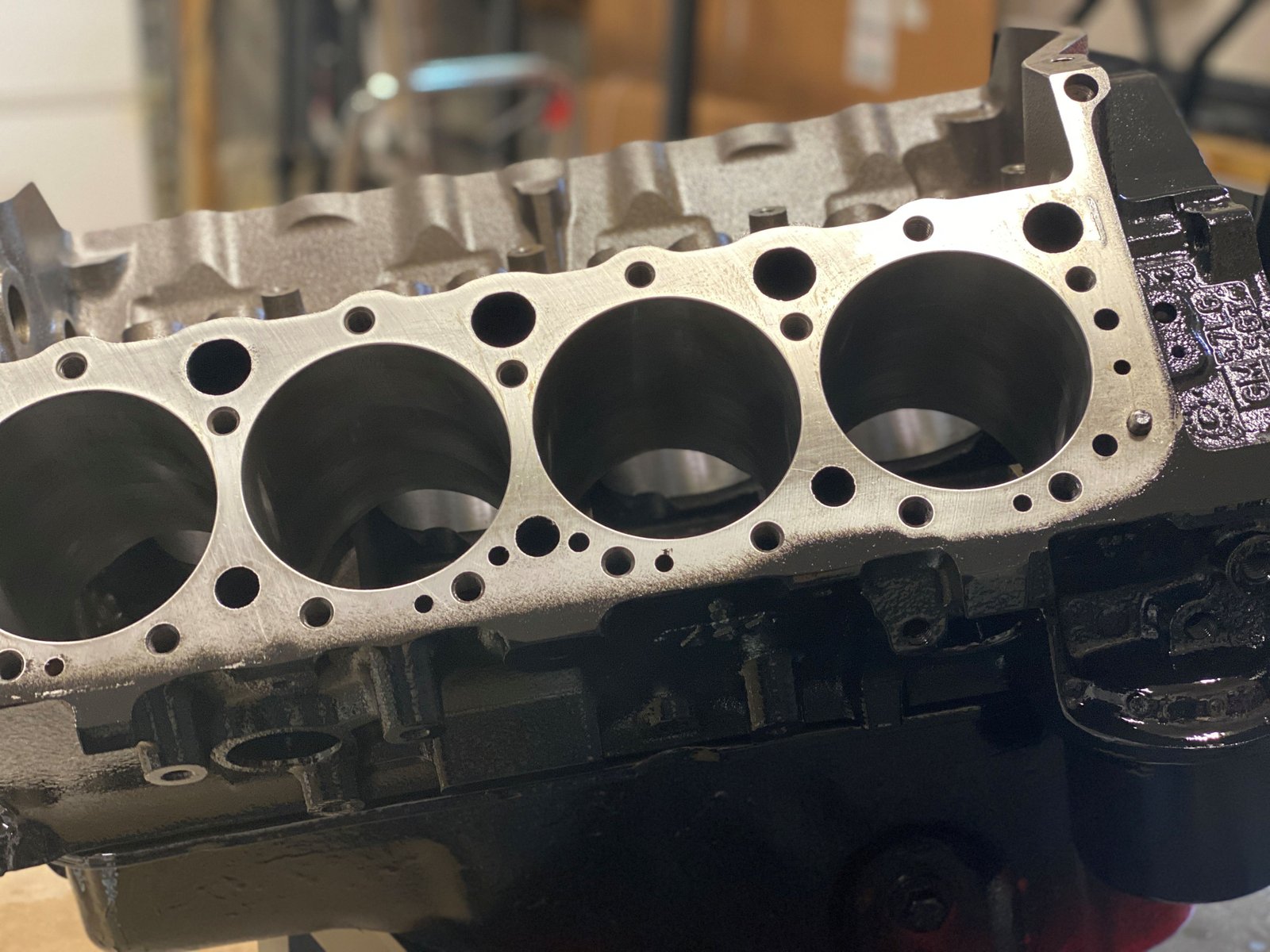
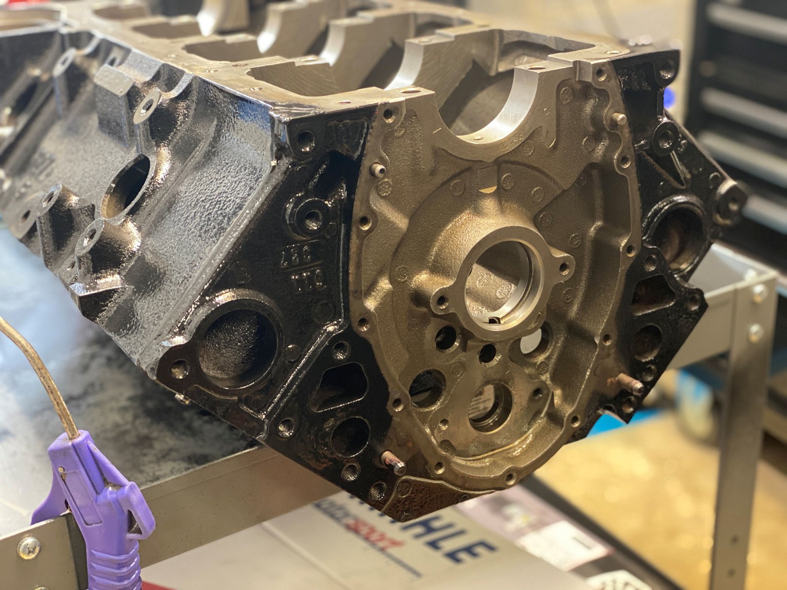
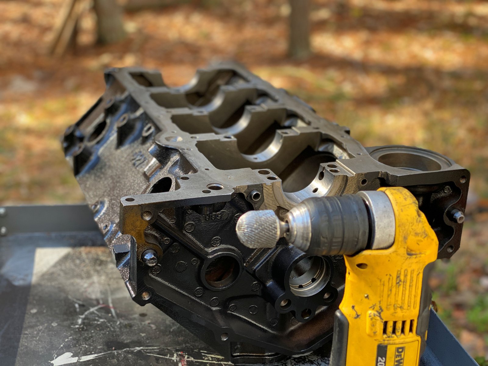
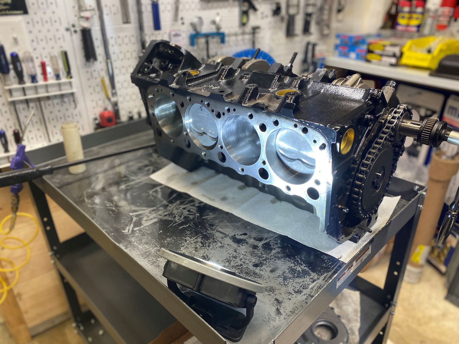
After cleaning the block it gets painted. I have a
sacrificial oil pan to help with masking.
|

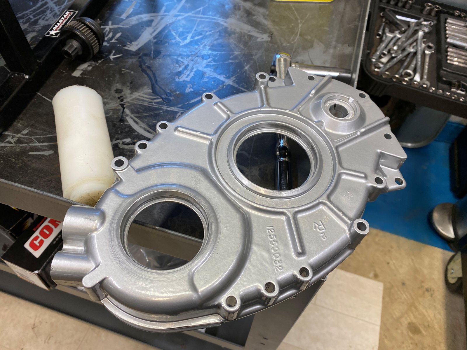
I also have a sacrificial timing cover. |

The paint dries fast. I did this in the morning and now for the
afternoon I can begin mock-up assembly.
|

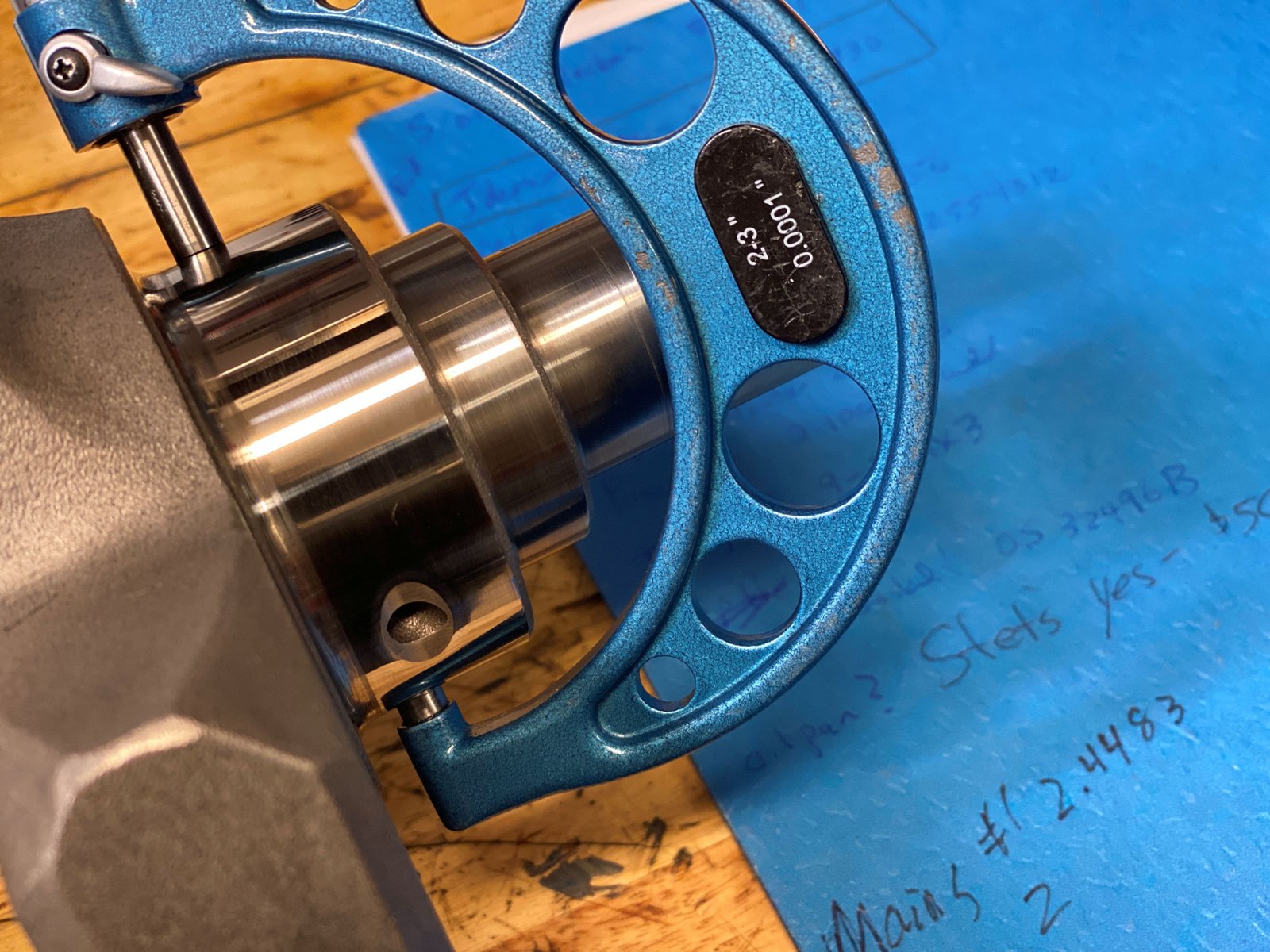
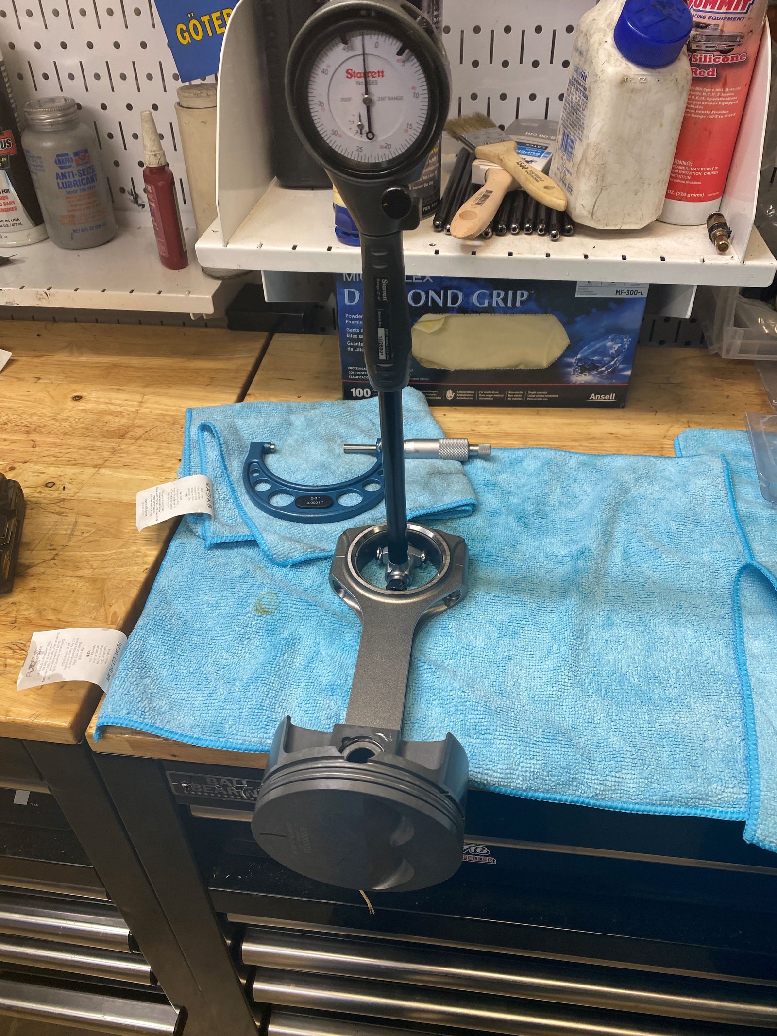
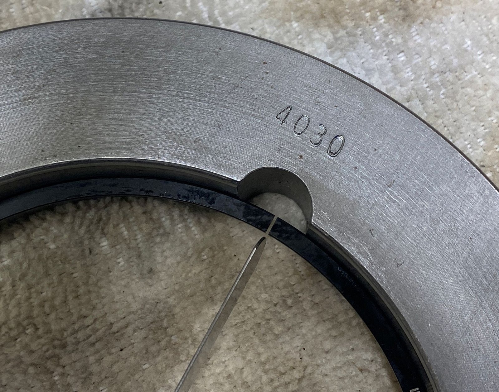
The crankshaft is getting the mains and rod journals mic'ed. |

Mains are all using X (.001 Over) bearings from King.
|

They measure from .0025 to .0035" |

|
To the left I'm measuring the 1st of 8
rods. With the King bearings they are all at .0025"
except this one here that is at .0023". Callies rods
are very very very consistant. |

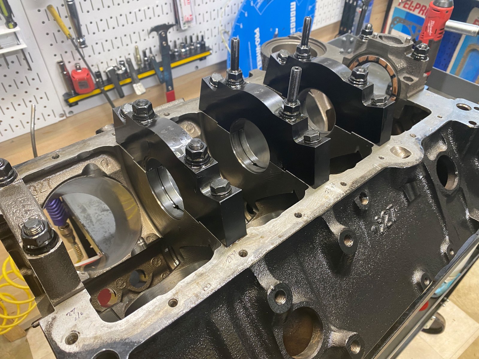
I need to take the caps off and install the crank.
|

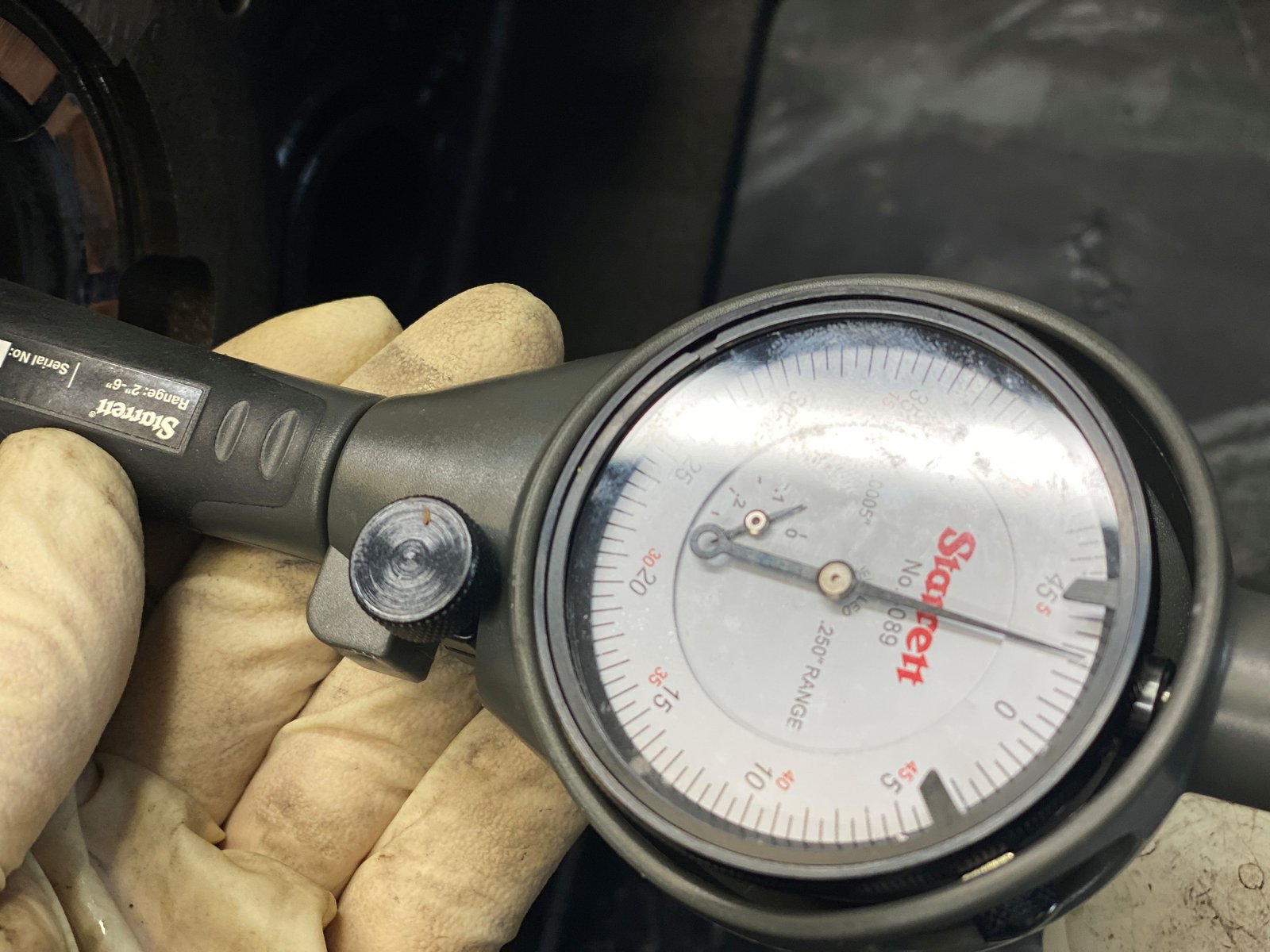
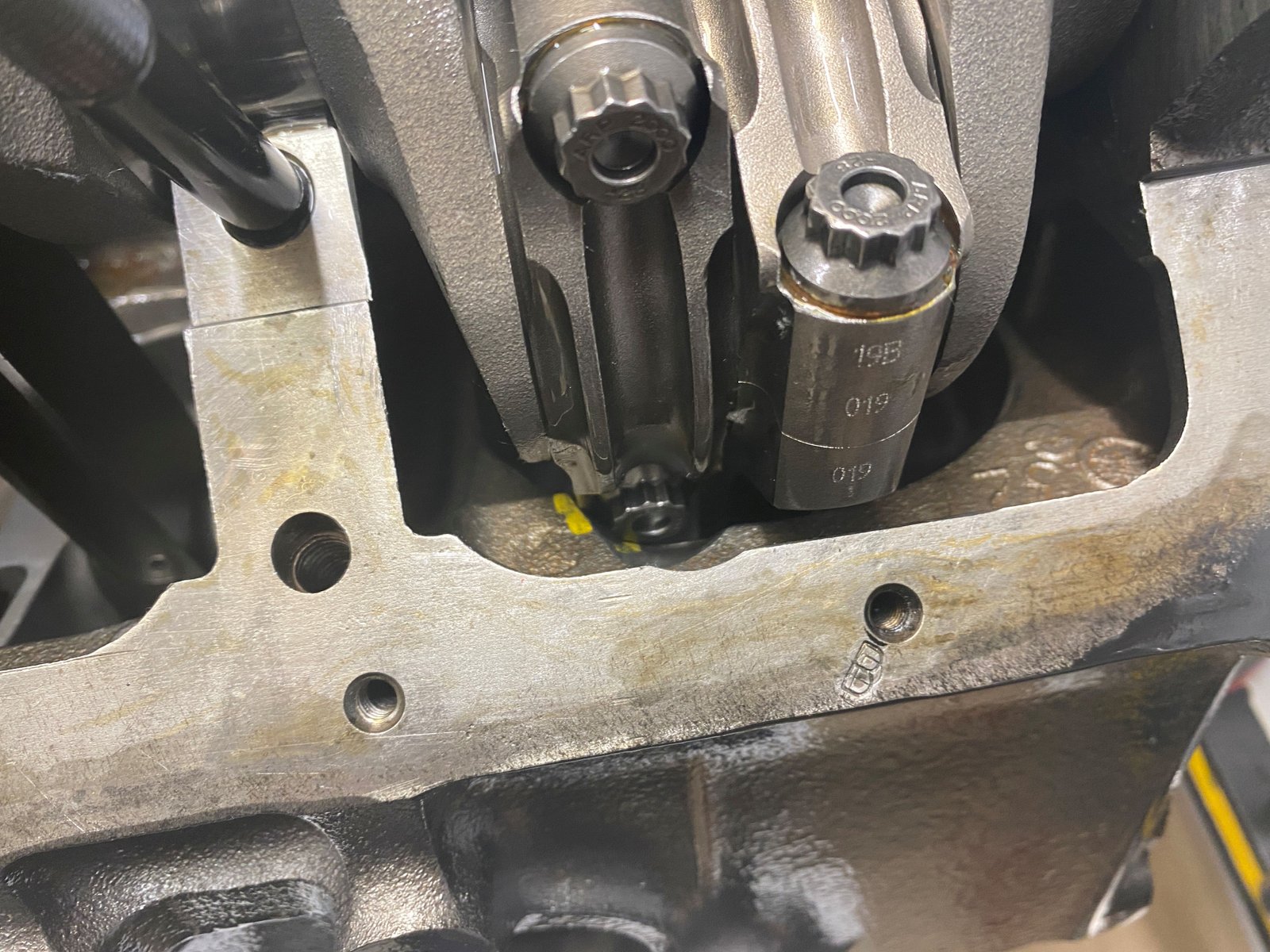
Here is my method of double checking piston to bore
clearance. I use a feeler gauge. This is a .003"
which fits slightly loose and the .004" is too tight.
So I'm calling it .0035" |

This is a mock-up assembly (unless all the rods have good
clearance). Here it is good. #1/3/5/7 are all good.
|

But on the other side I need to do more clearancing.
(#2/4/6/8). Just a little bit but still the whole assembly
must be torn down and then I grind in the spots marked and then do
the final wash. I leave the camshaft bearings out on purpose
until I know for certain that I don't need to do additional
grinding. |

|
 |

OK, time to do the additional clearancing and then washing
(hopefully a final wash)
|
 |

I also threaded the front oil gallies.
|

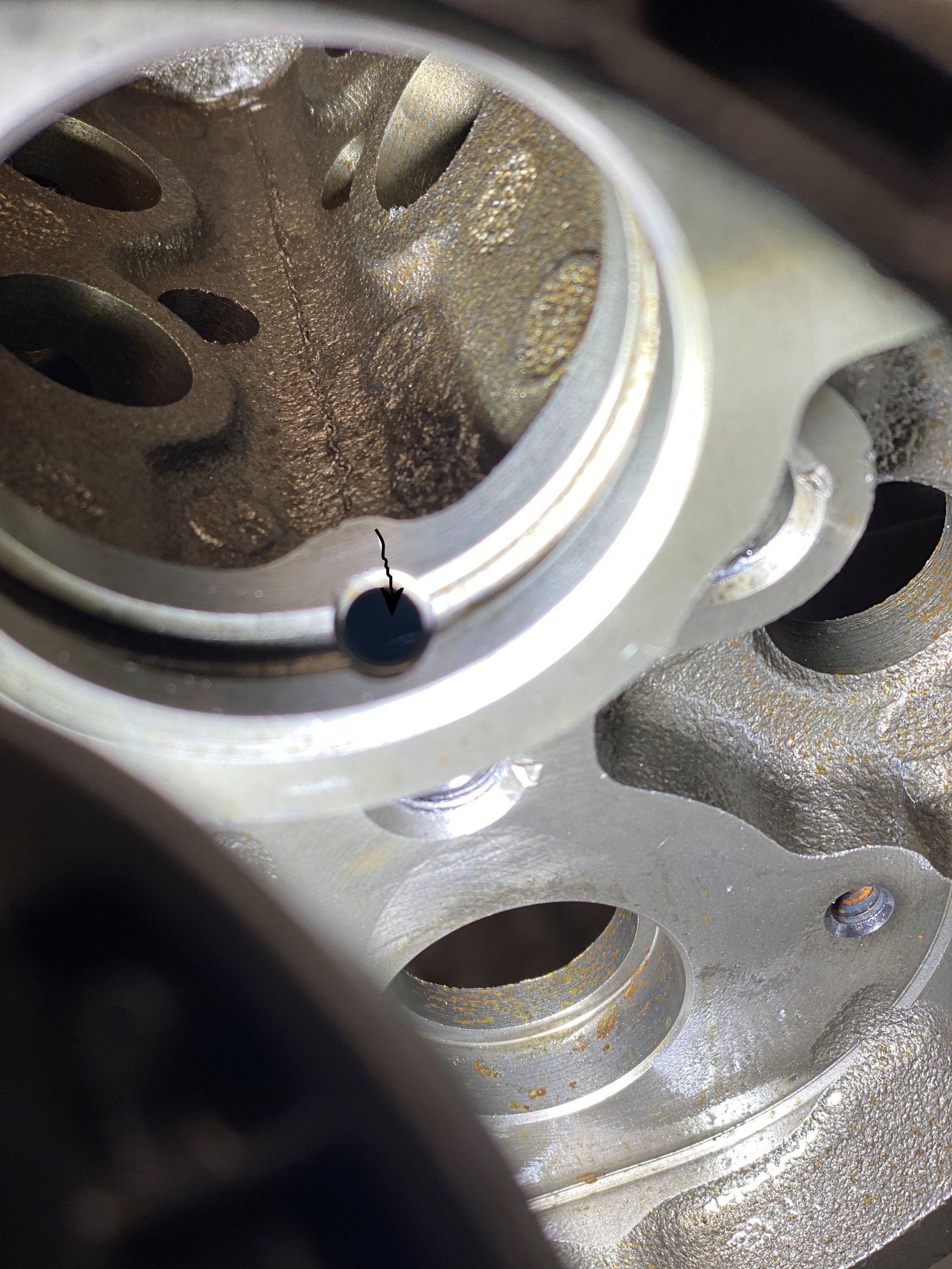
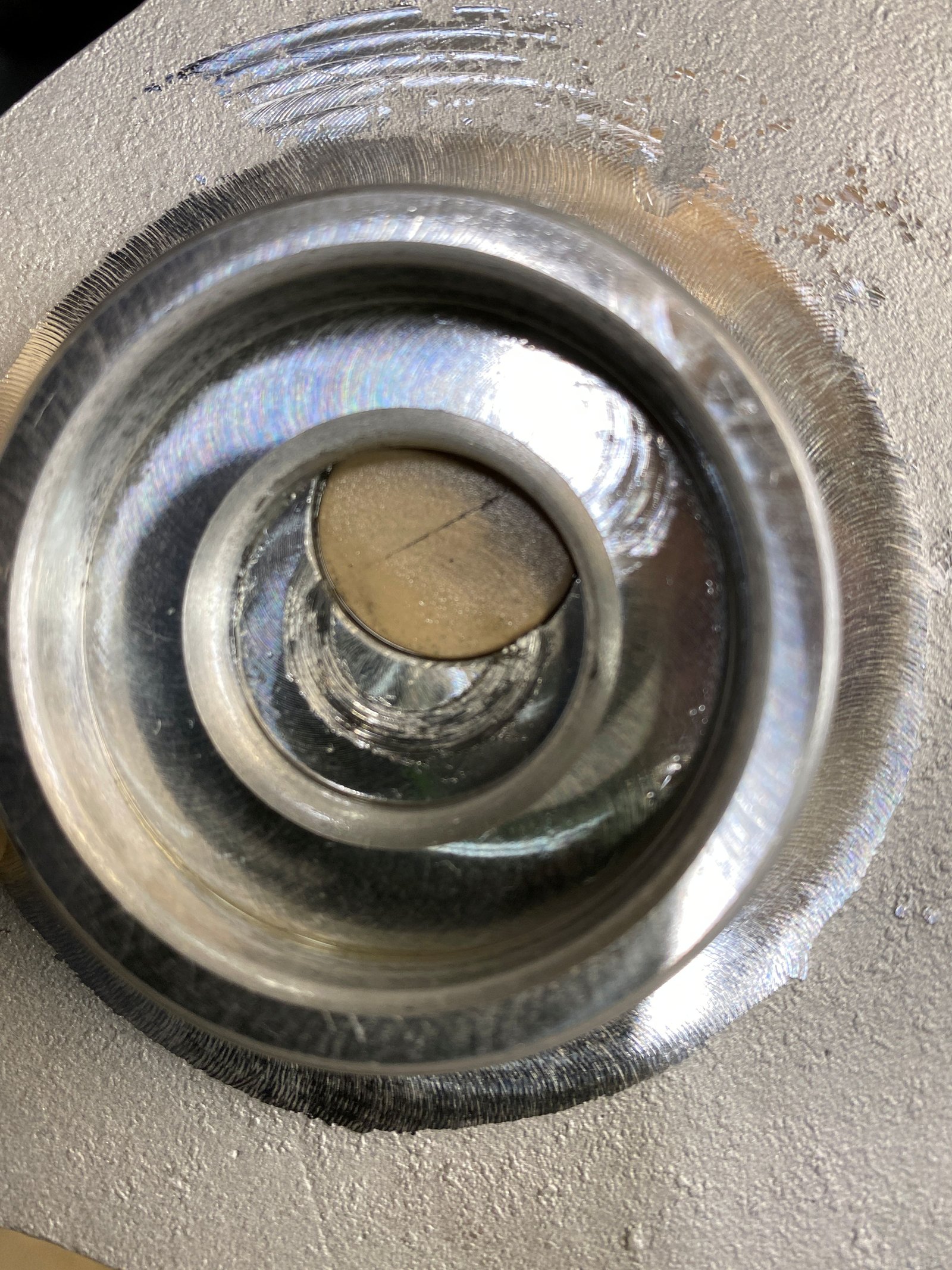
What's that weird crack at the cam journal? It's not a
crack but line I made on the photo to point to the oil galley
hole. |

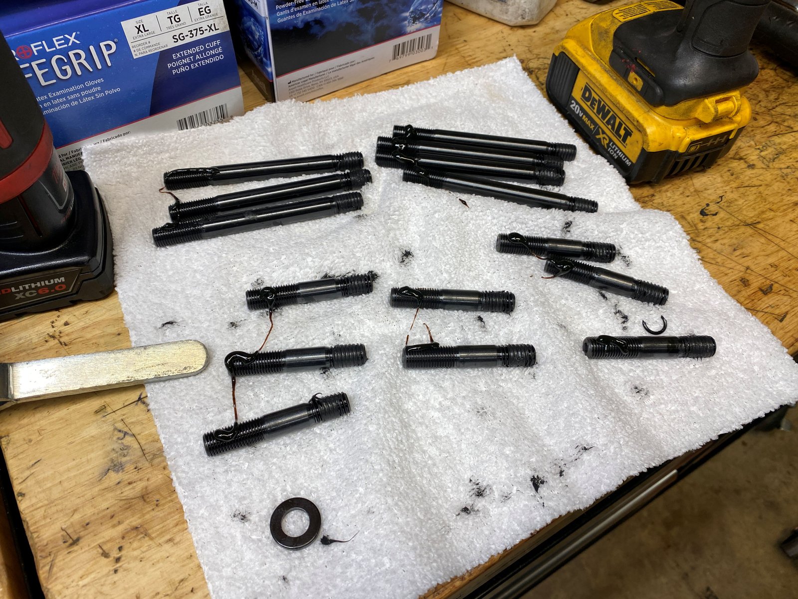
Oil gallies plugged and the lifter gallies have oil weep holes
in the plugs.
|

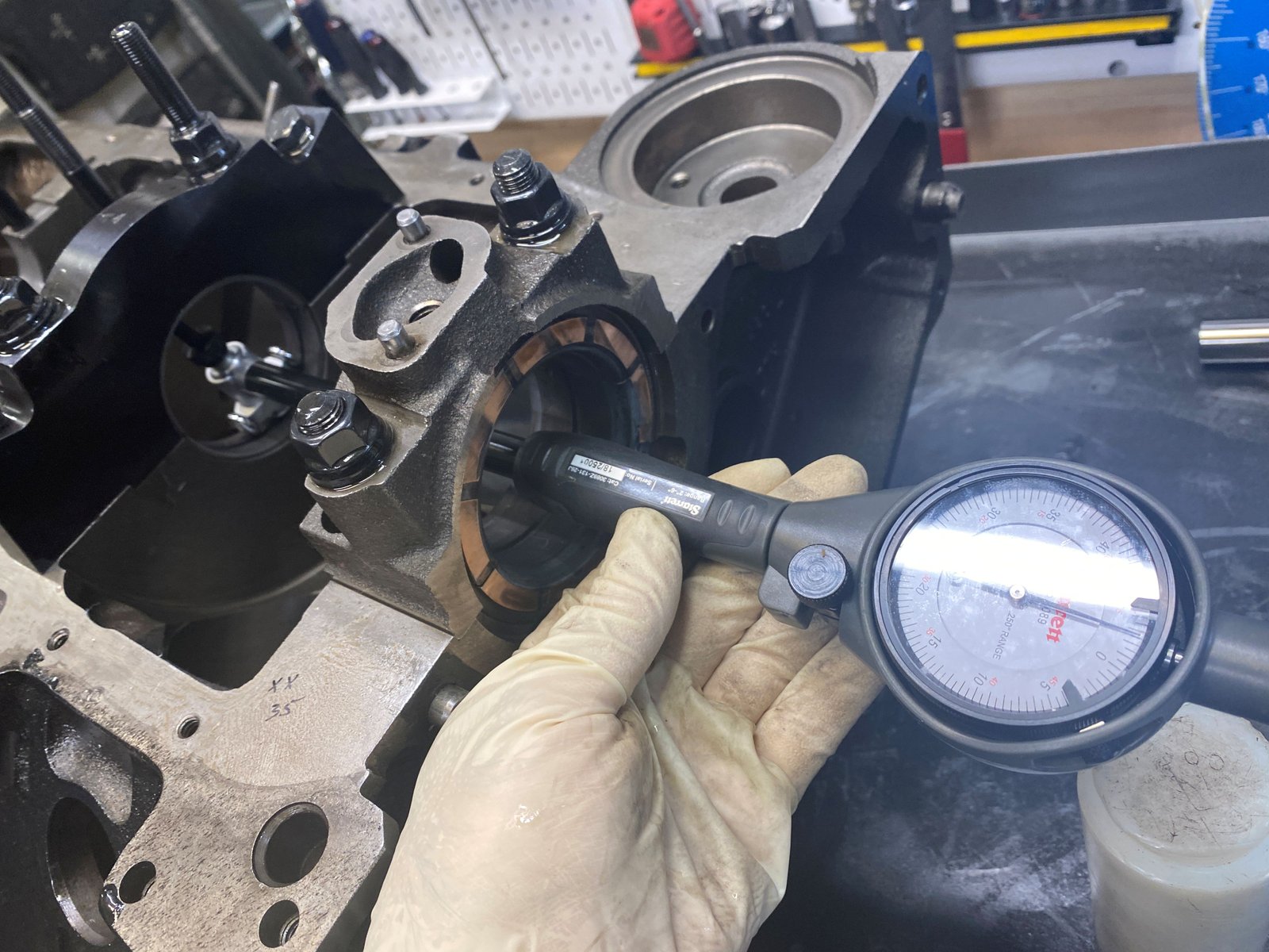
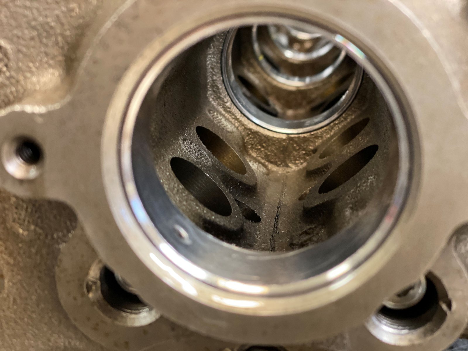
Cam bearings installed. That means I'm pretty confident
that all the block clearancing is finished. |

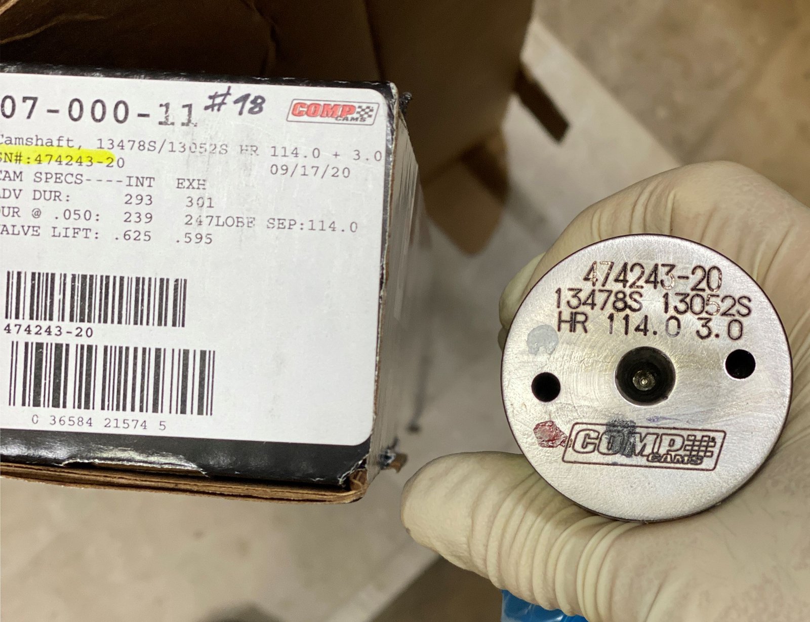
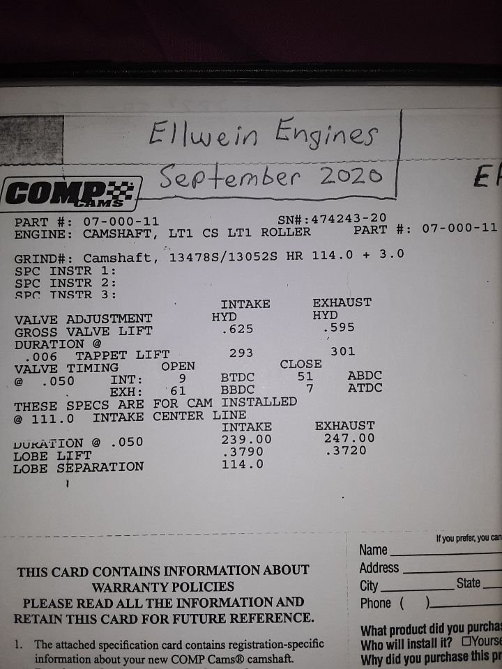
Camshaft spec'ed by Dennis Staff at FastCat Porting Service.
|
 |

Photo verification of oil galley plug installed.
|

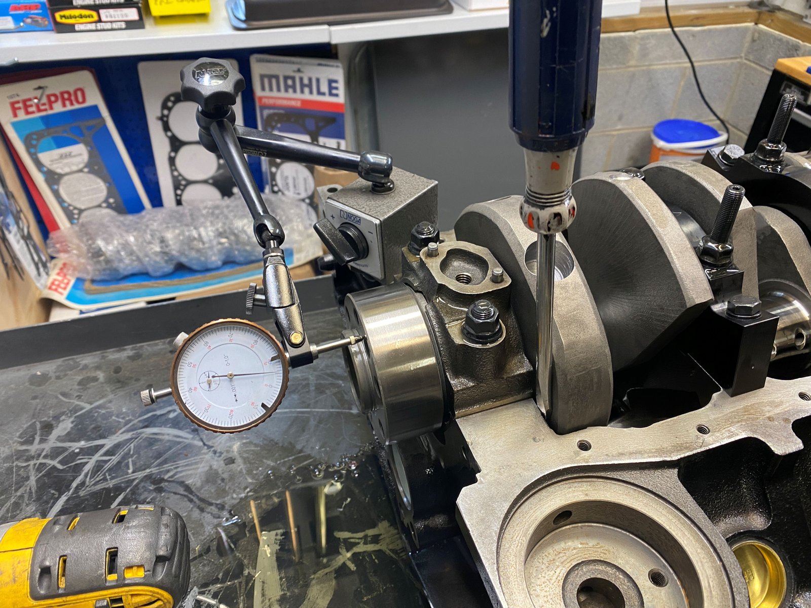
Thrust is .006" |

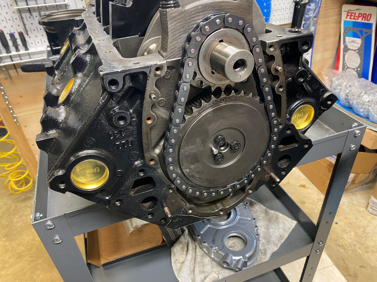
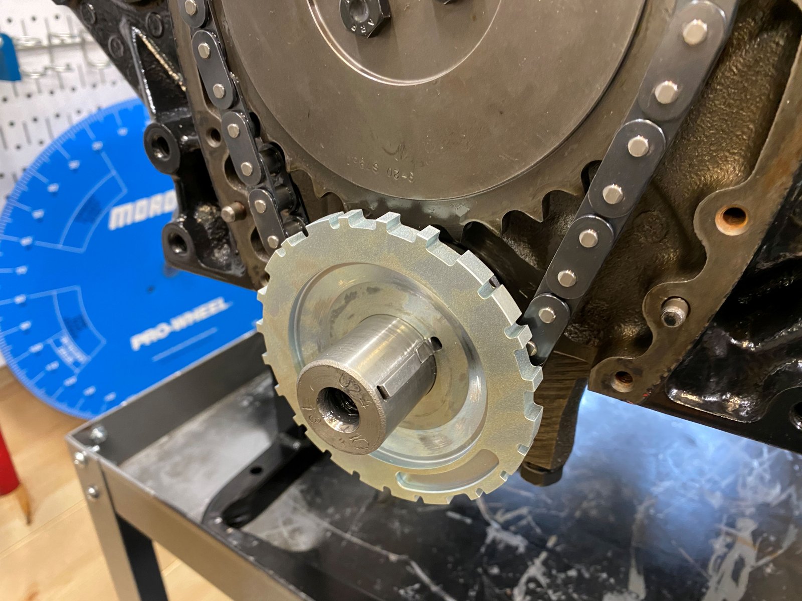
Cloyes timing set.
|

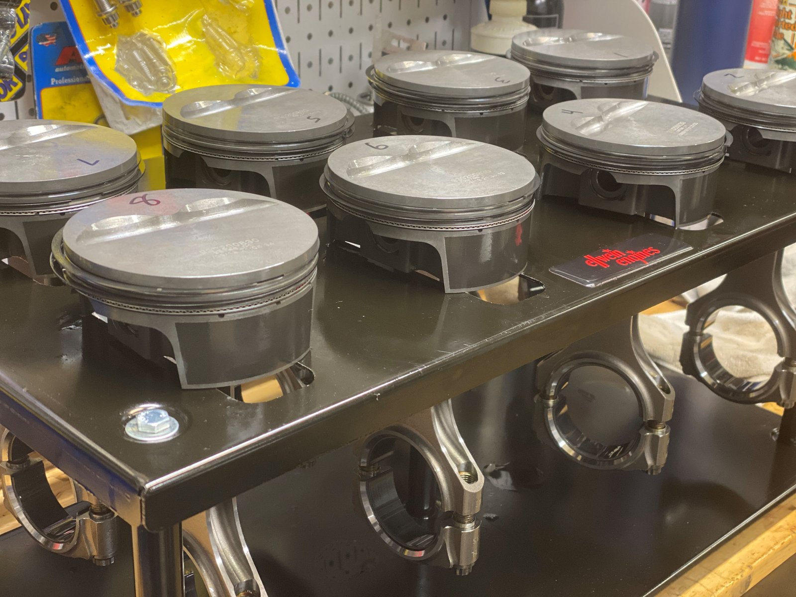
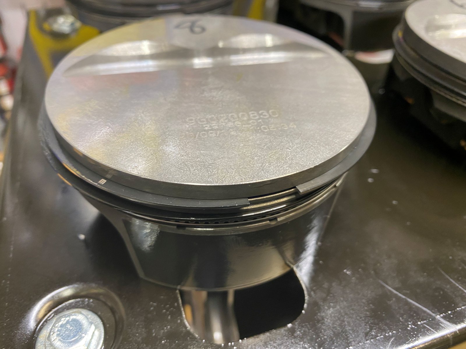
Time for ring filing. |

|

Top ring .024" and 2nd ring .020" as per Mahle spec
for 200 hp nitrous. Whenever nitrous is involved Mahle will
recommend that the 2nd ring is gapped tighter (for oil
control). |

|
 |

|

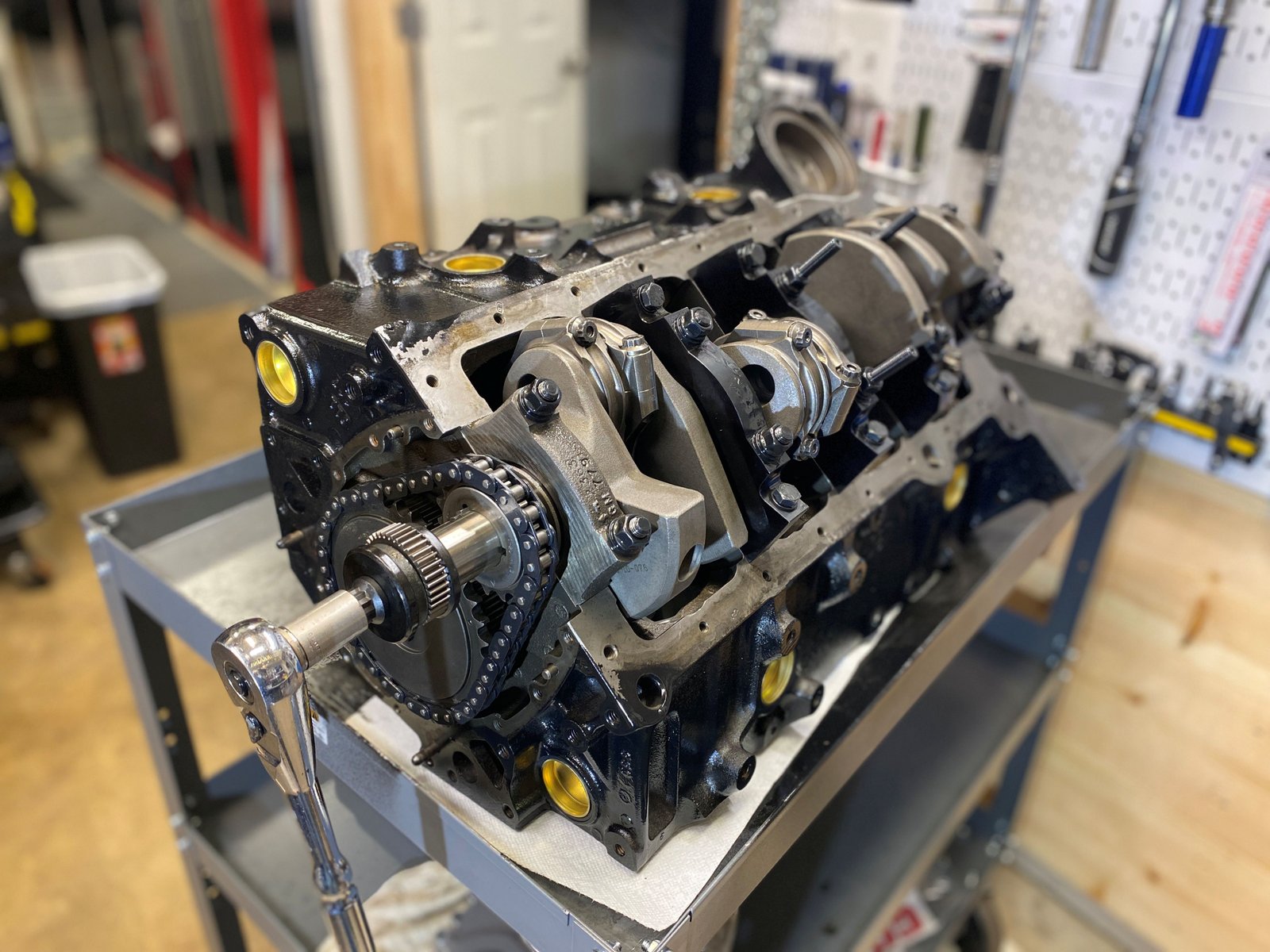
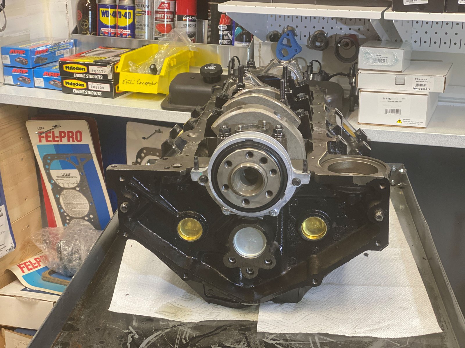
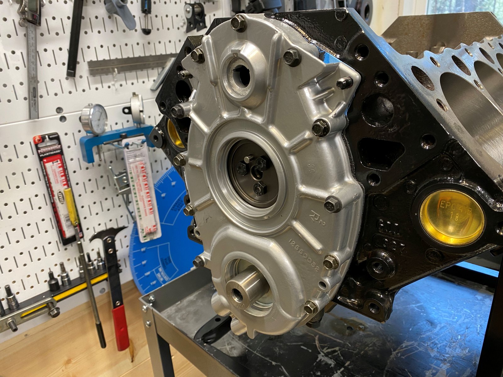
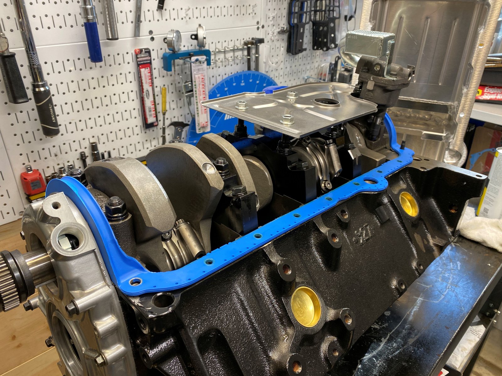
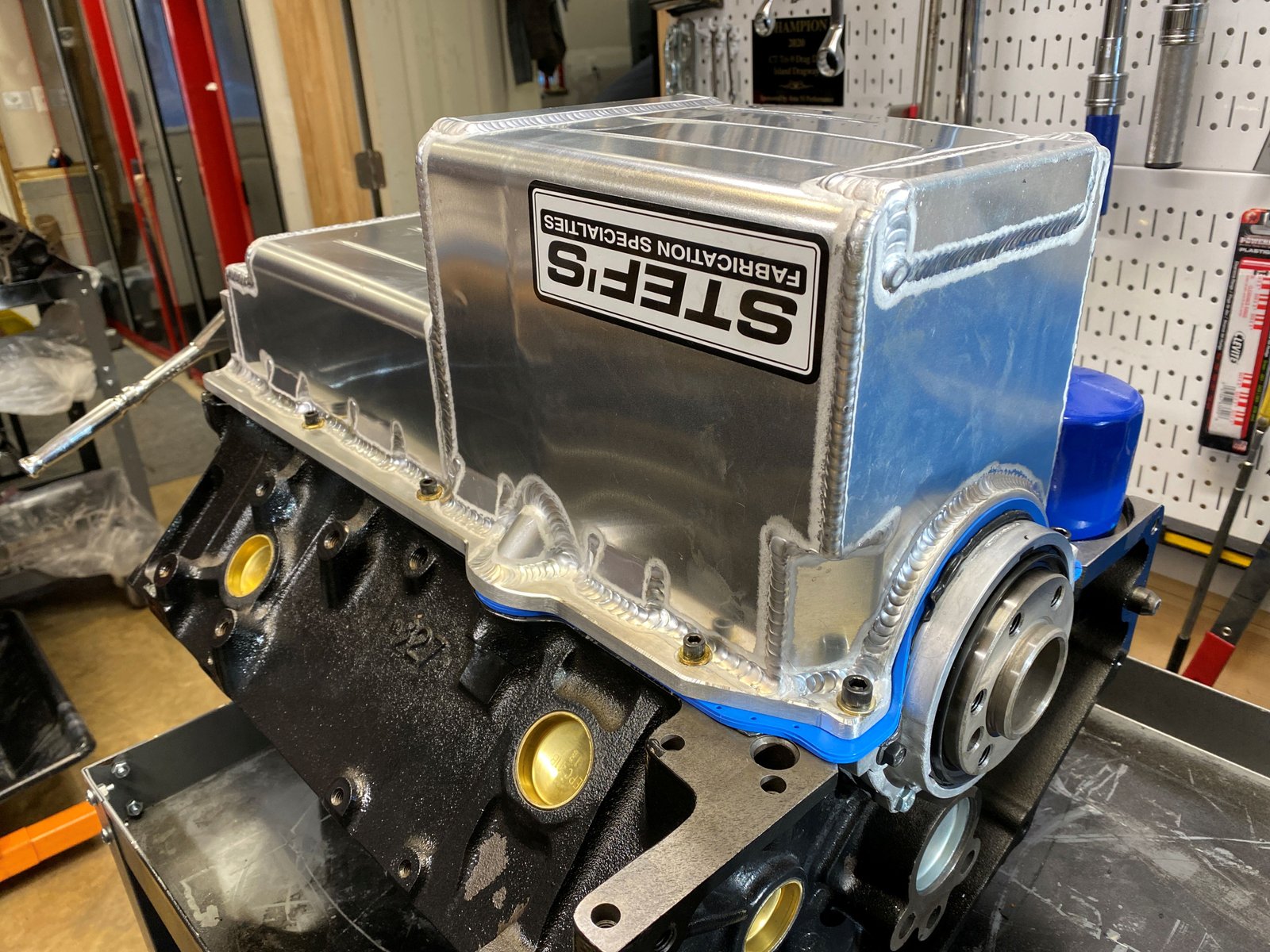
Rotating assembly fully installed. |

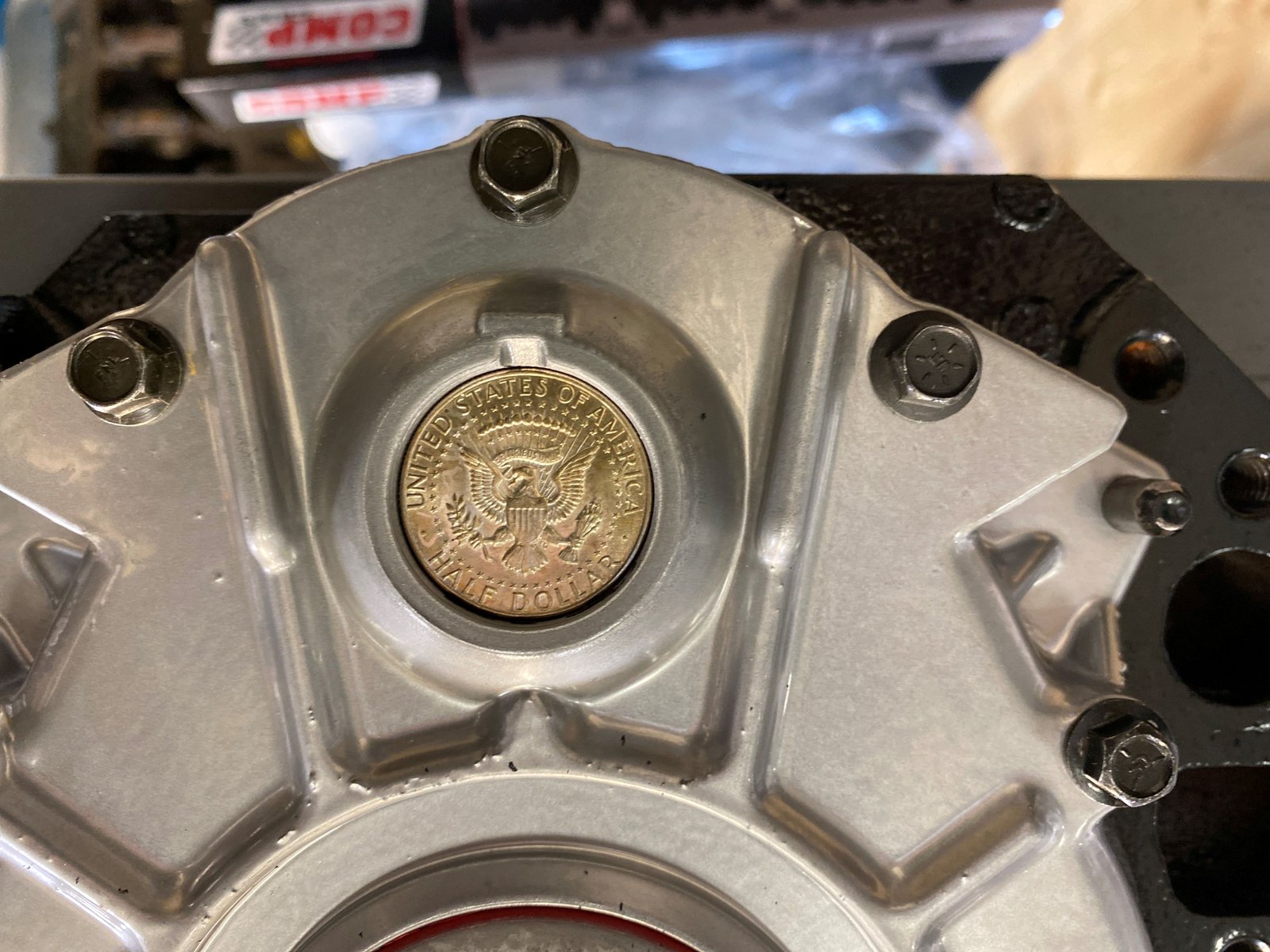
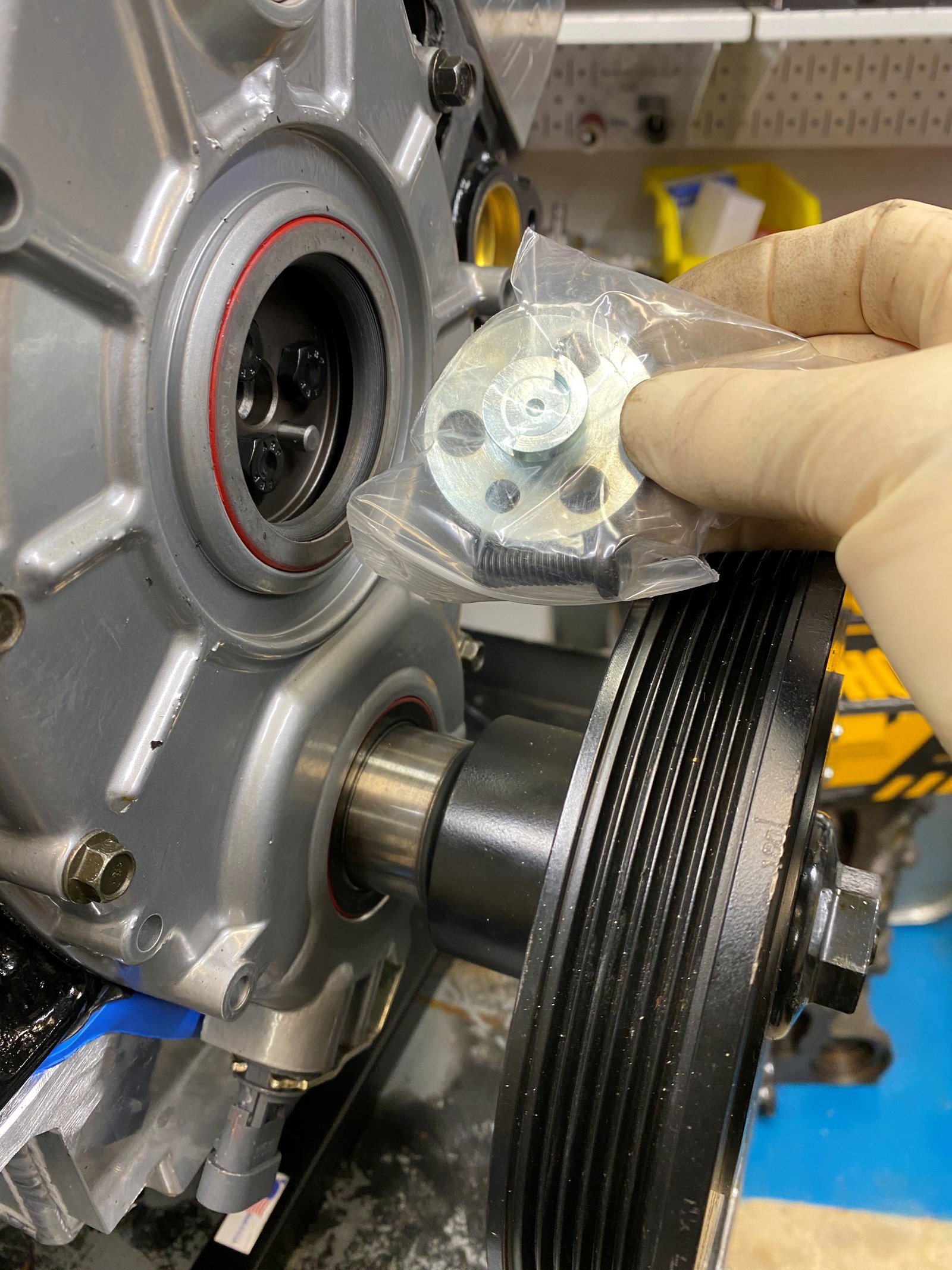
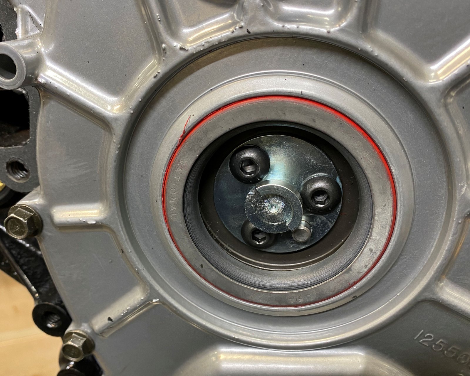
New GM rear main seal and housing.
|

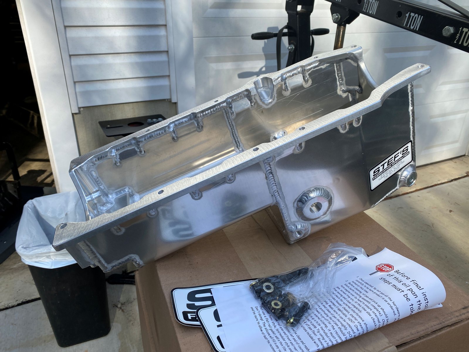
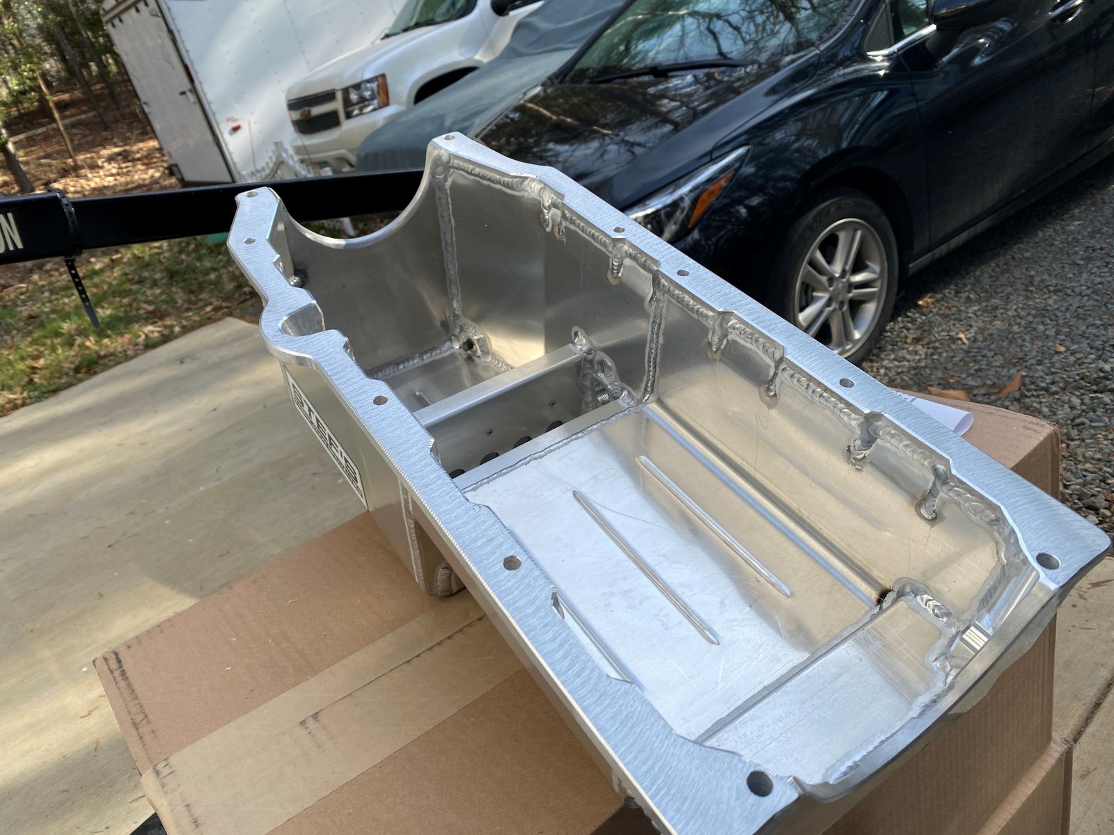
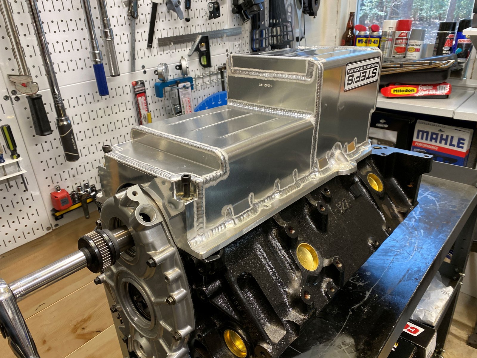
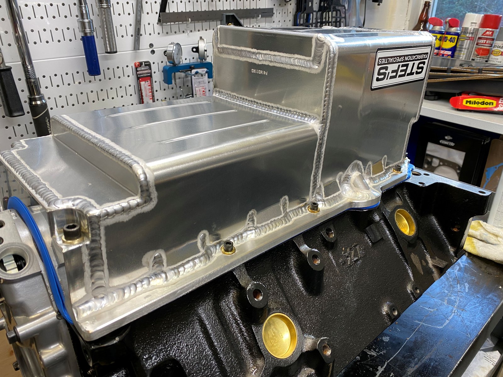
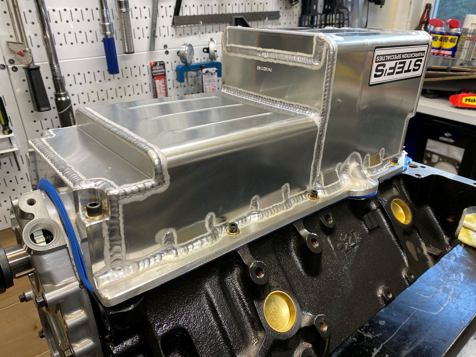
Stef's oil pan arrived a few weeks ago. This is built to
my spec. |

|

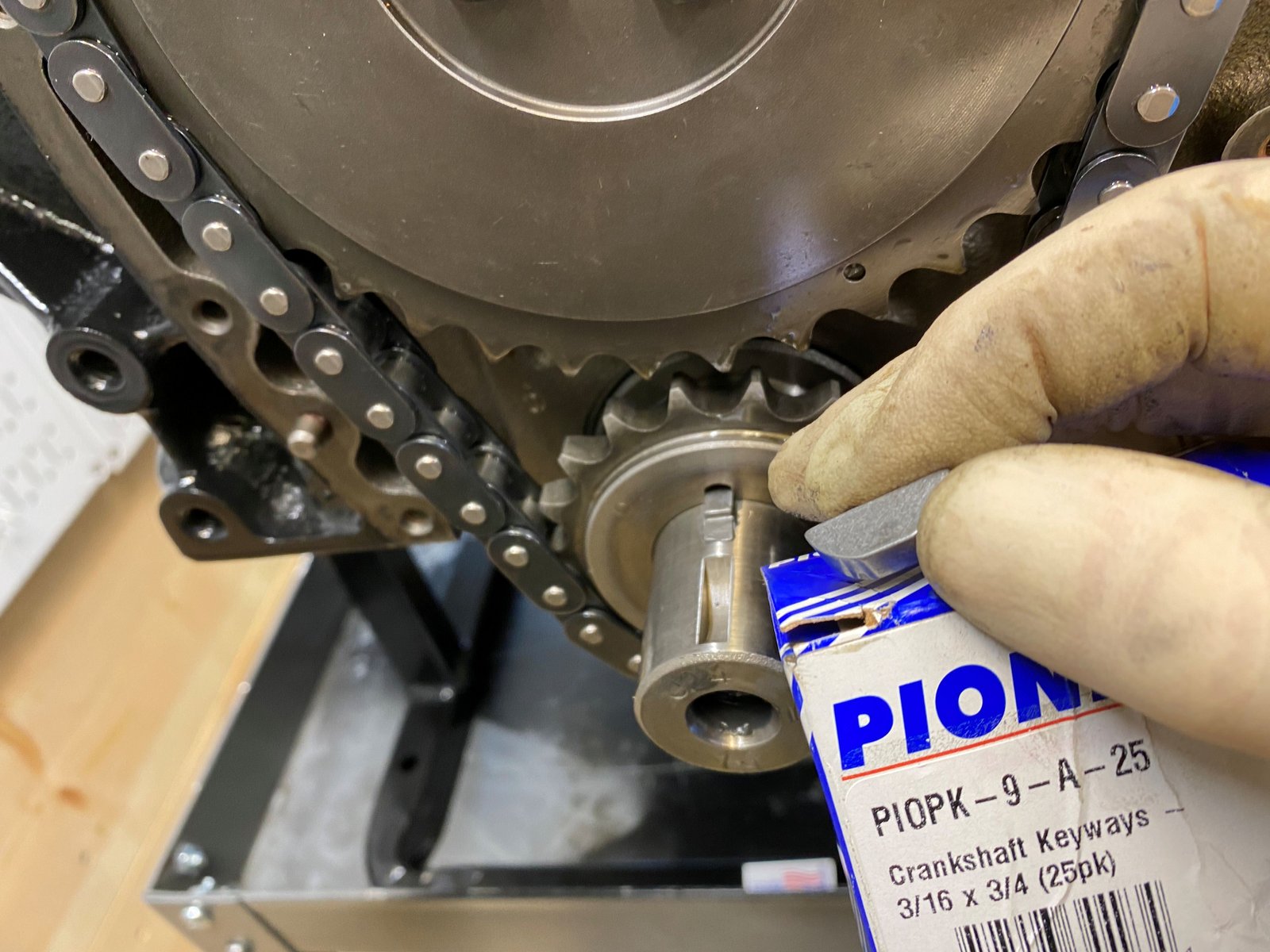
Eagle crankshaft do not come with woodruff keys. I use
these from Pioneer. |

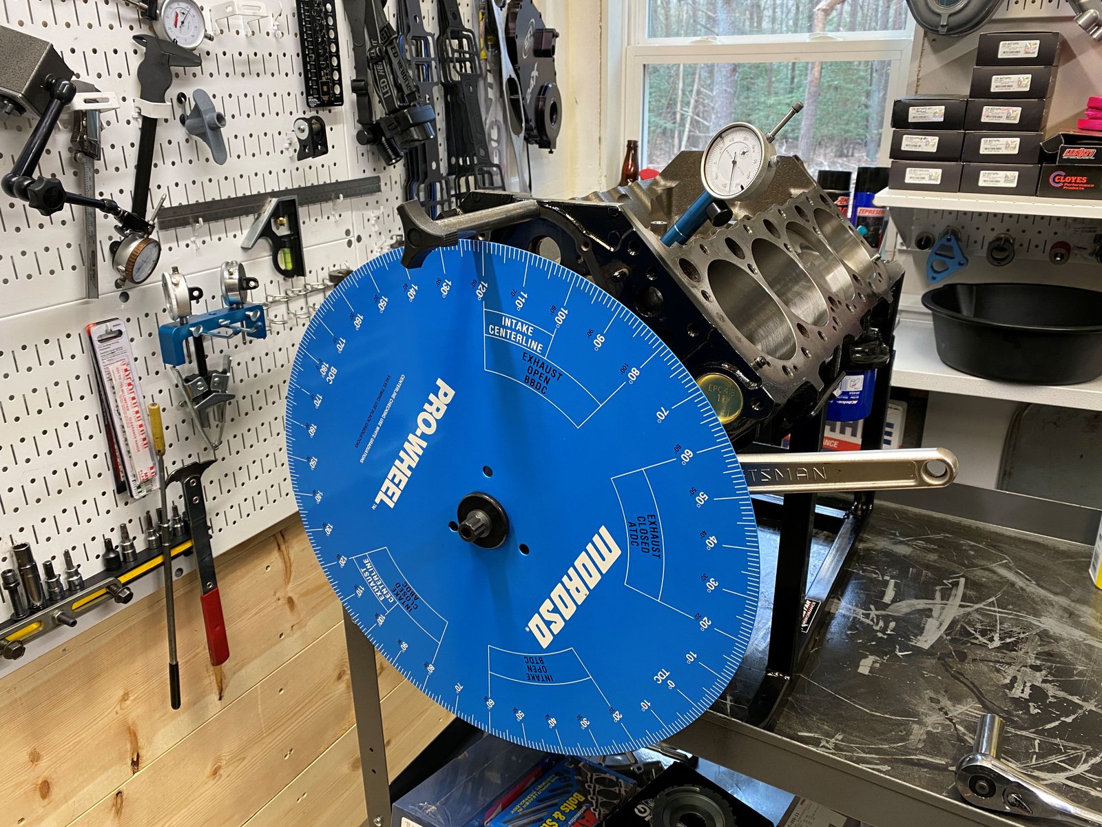
Camshaft degree check. Timing set is a zero. Intake
lobe verified to be exact as the cam card shows.
|
 |

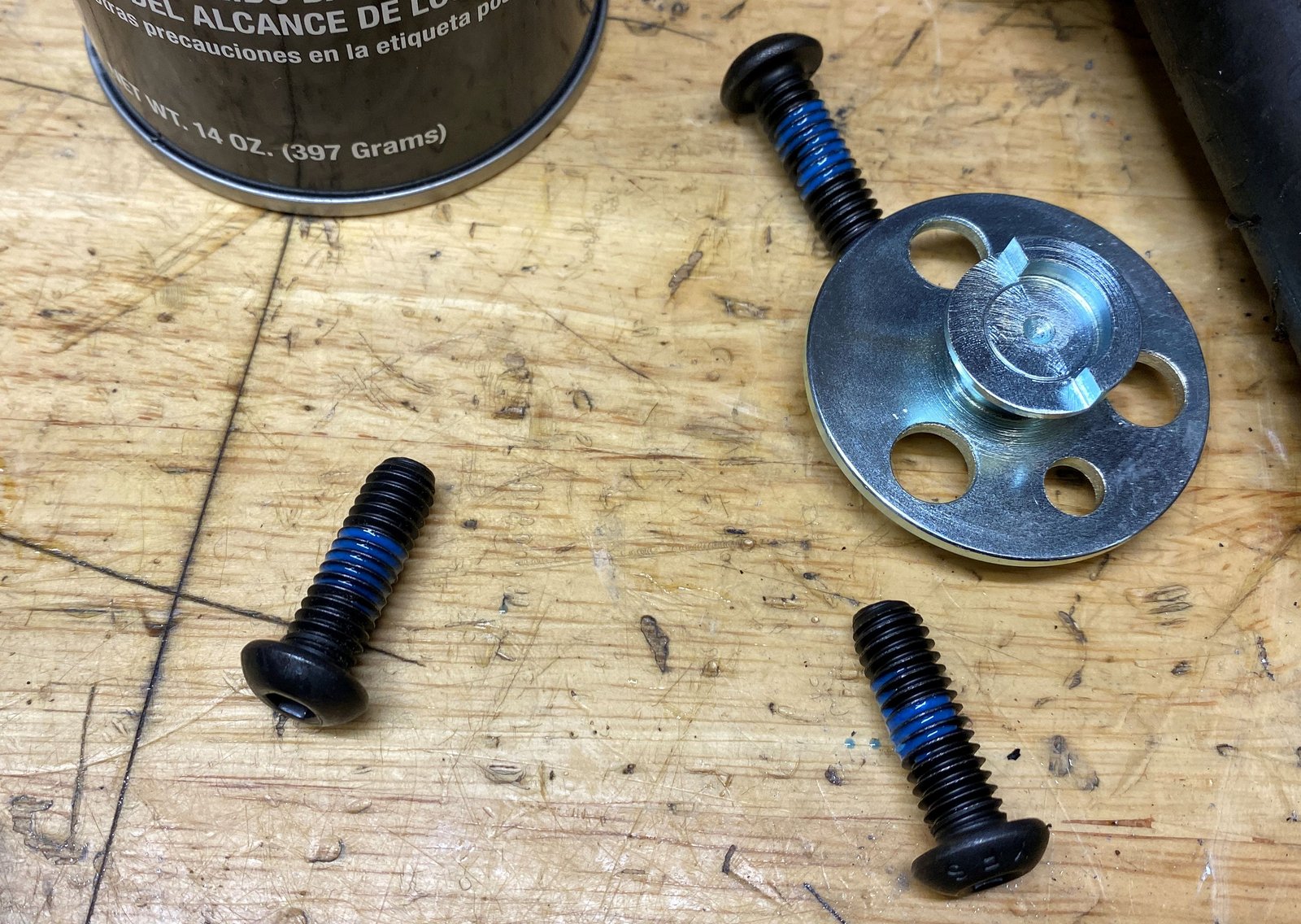
EFI Connection 24x crankshaft reluctor. The car will be
running Holley Terminator. This is EFI Connection #120-0070
|

Locally powder coated. |

|

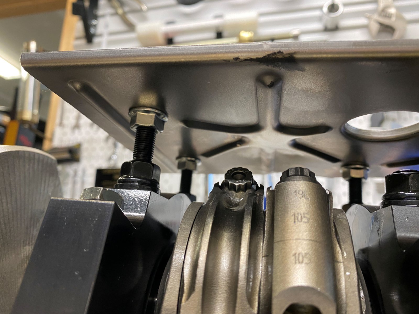
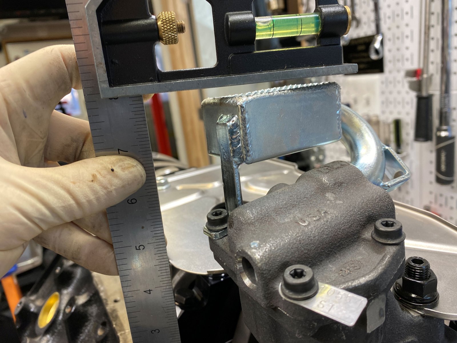
Test fit of Stef's pan. Usually need to clearance at the
rear crankshaft counterweight. |

Yes. That is the spot.
|

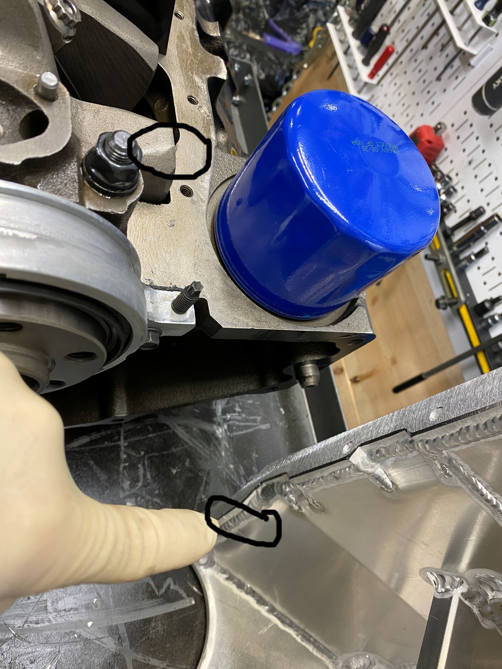
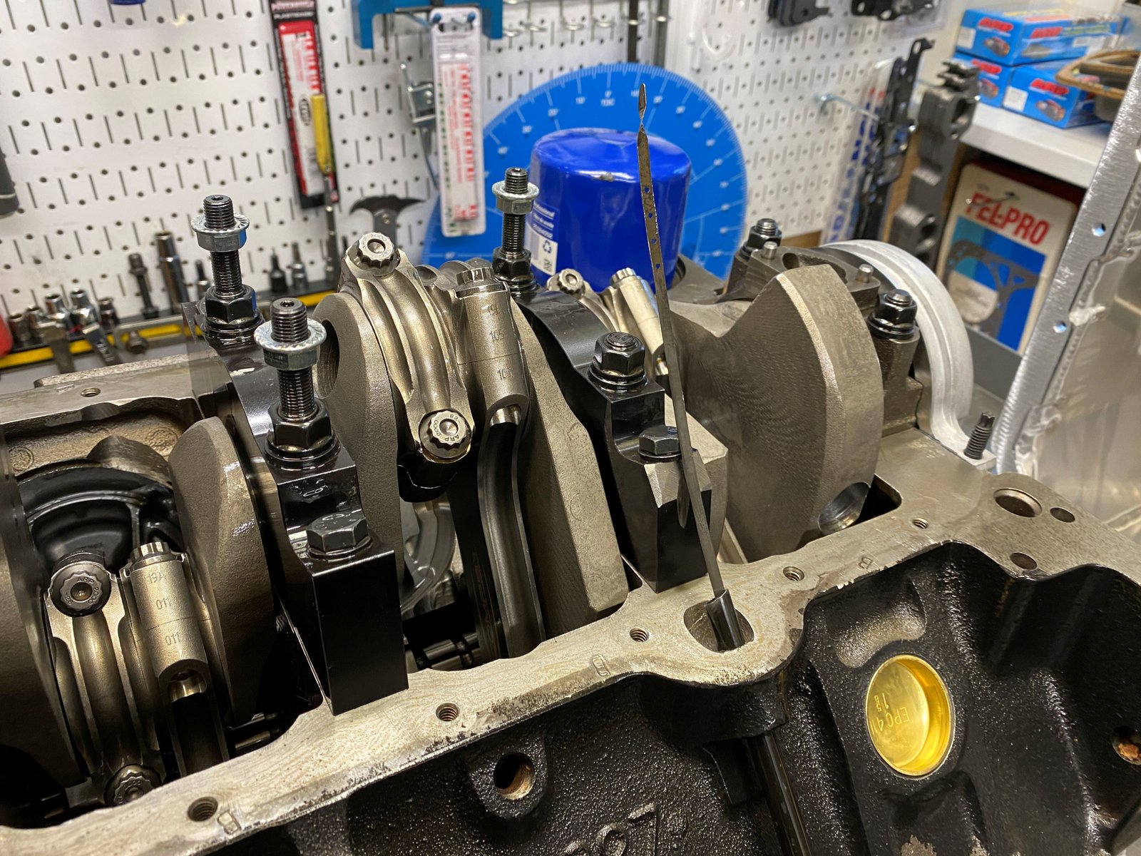
Dip stick test. It will make it past the main cap. |

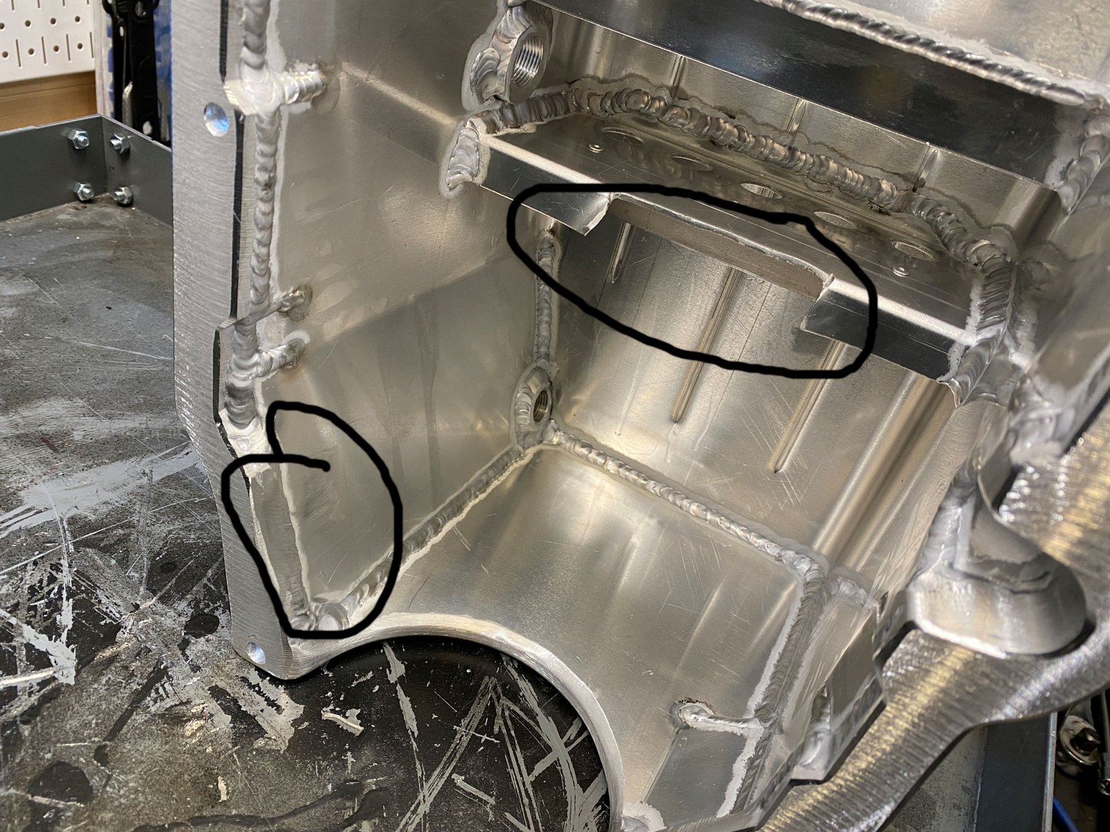
Cut out the trap door support to allow the dip stick to
pass. The area at the pan rail (circled to the left) is where
I grind to clearance the crankshaft.
|

This photo is for reference. I scratched the windage
tray while bending it away from the rods. Also got some RTV
on the windage tray. |

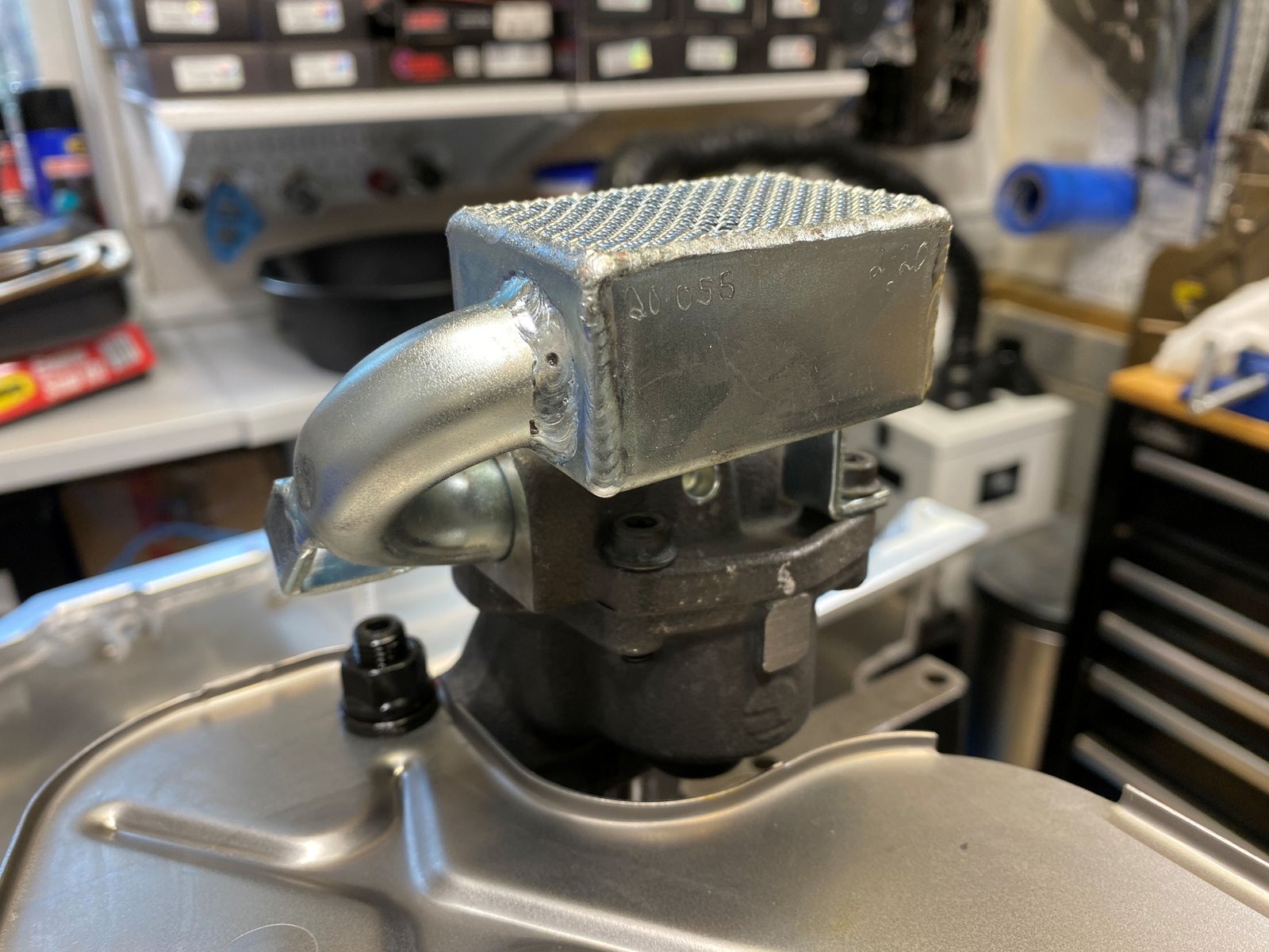
Melling 10554ST oil pump and Canton 20-055 oil pump pickup
|
 |

|

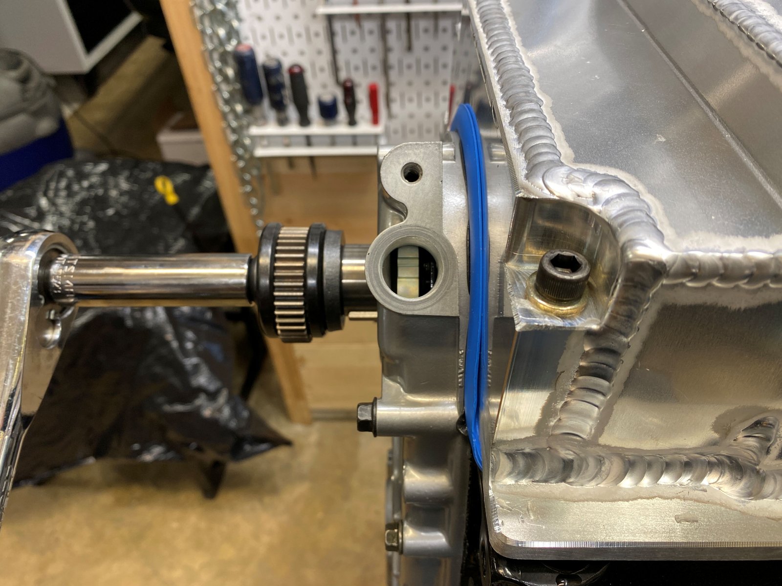
Pan on. Here is the reluctor alignment view.
Pretty good. Not exactly centered but it is a thick
reluctor. |

|
 |

|

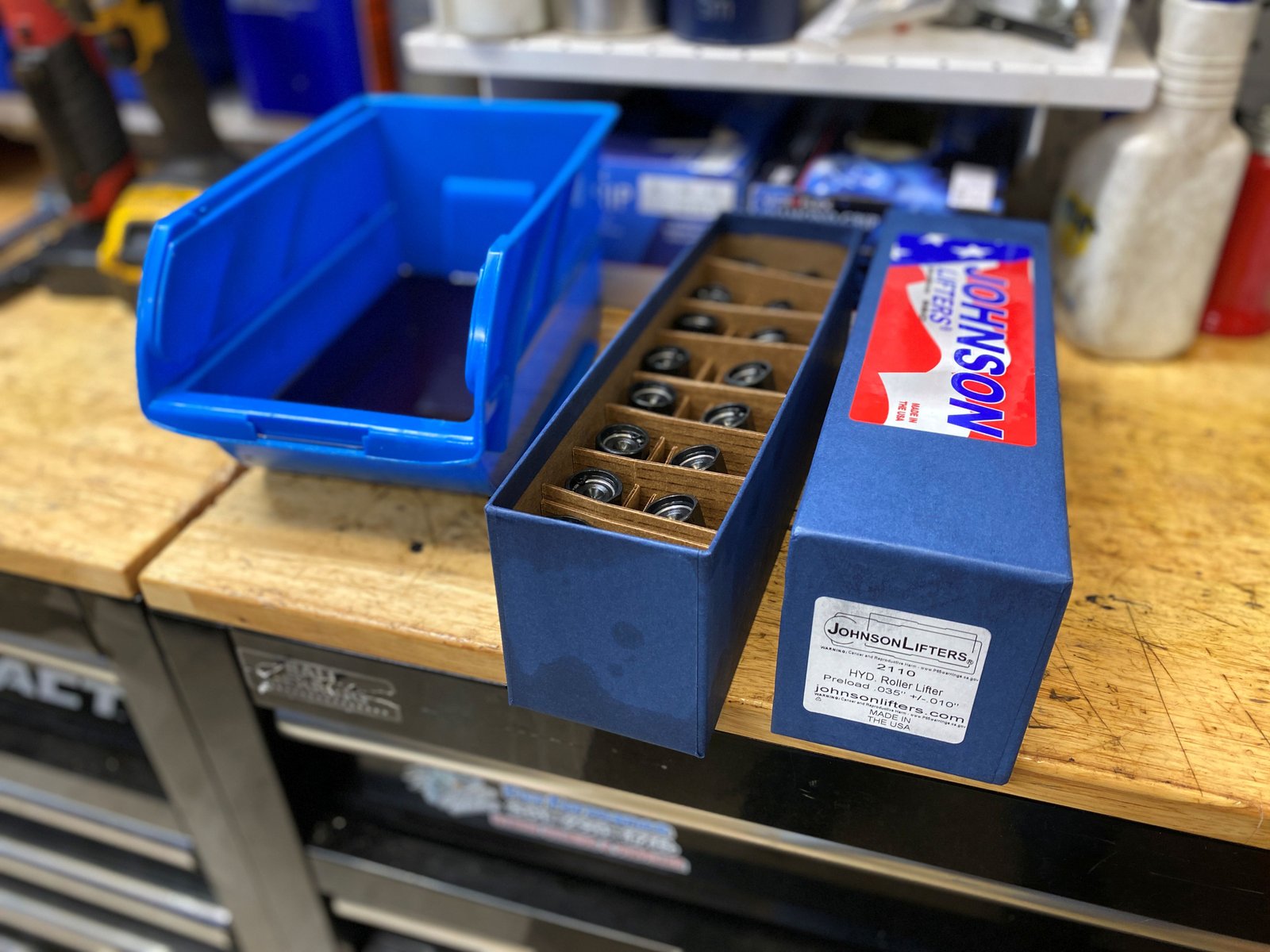
Kennedy $.050 for plug. |

Johnson lifter will soak in oil for the evening.
|
More assembly soon. |

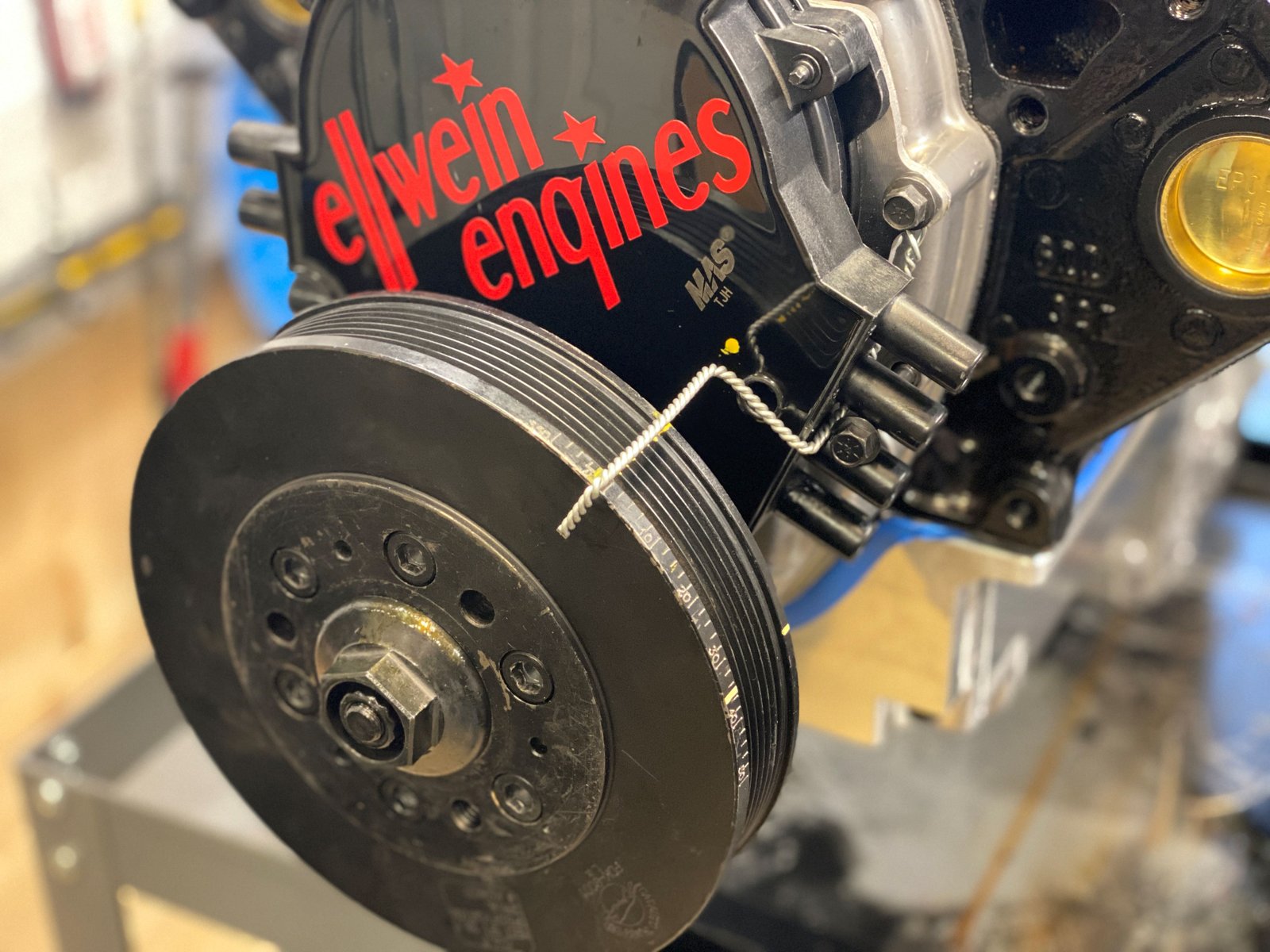
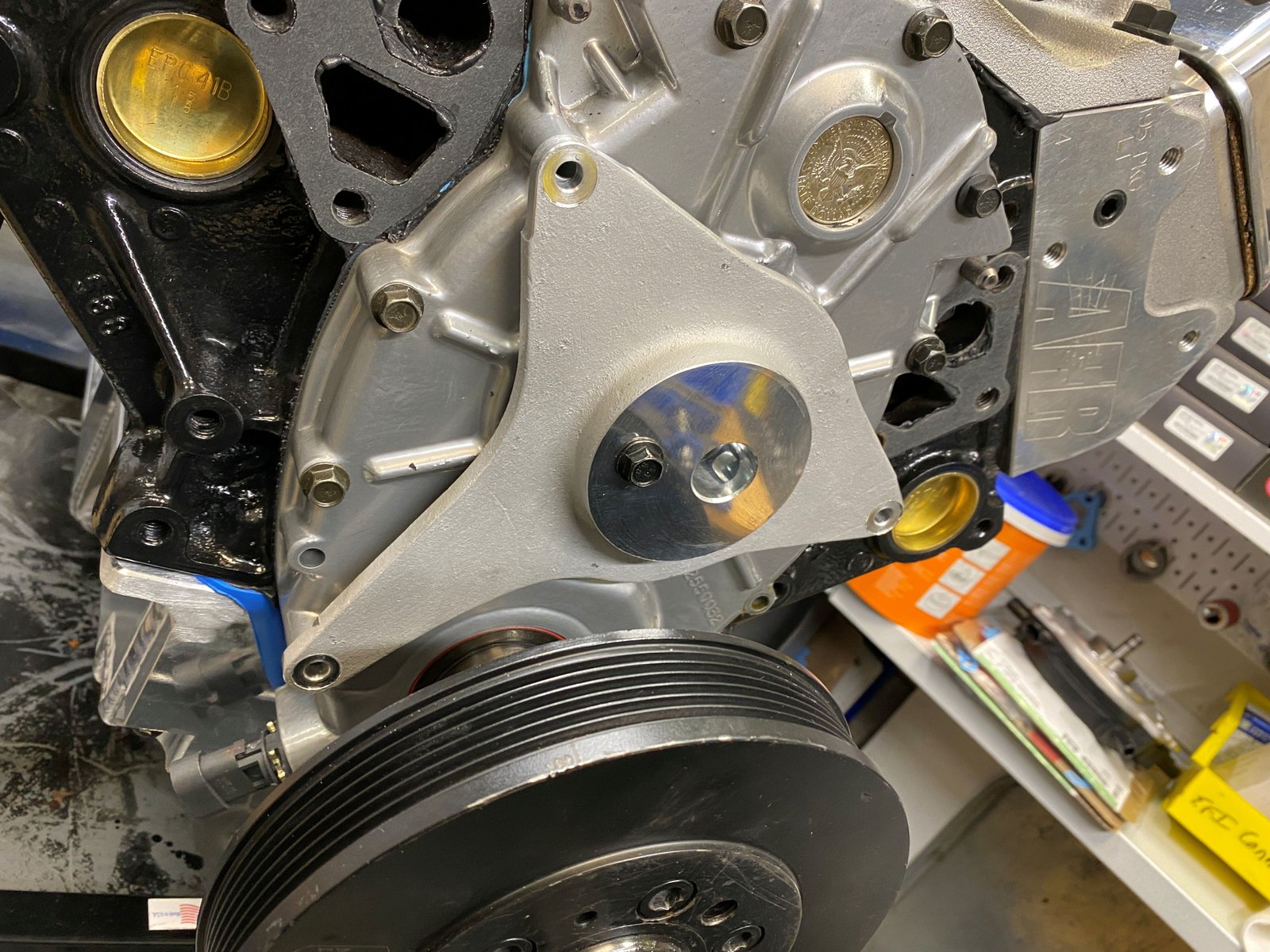
This is my dyno damper and dyno timing pointer.
|

Also..that is my optispark which is just filling the hole. |

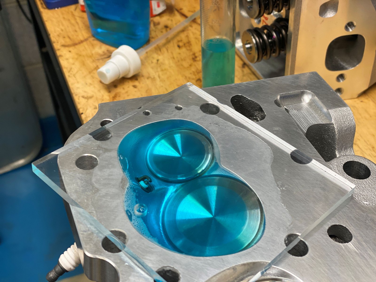
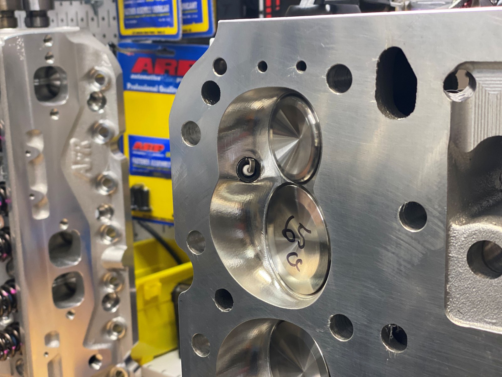
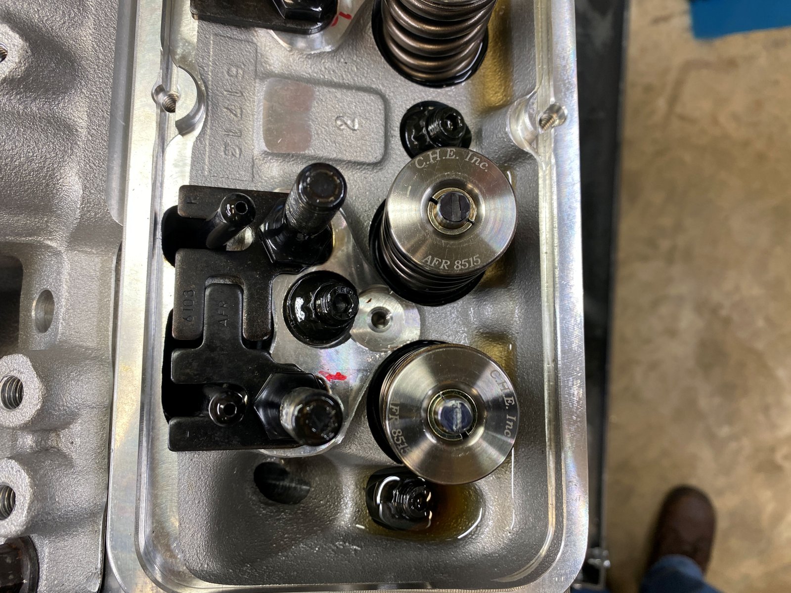
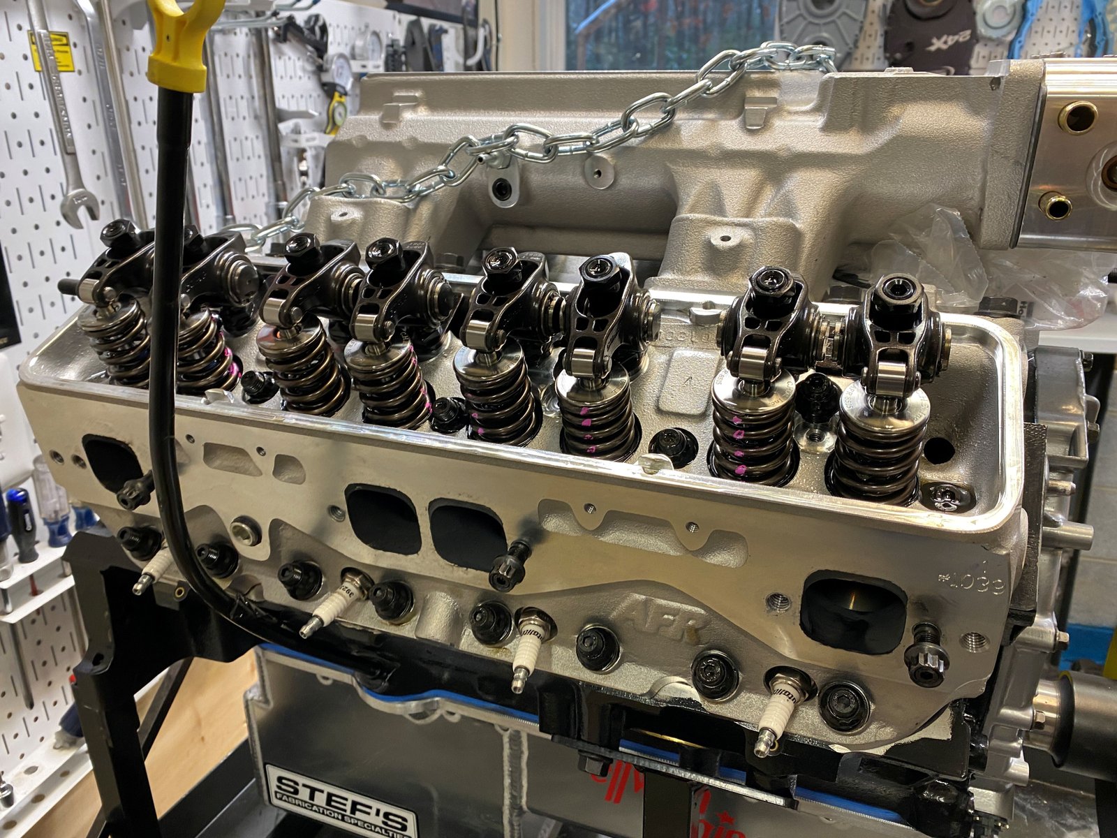
Time for the AFR heads. volume check.
|

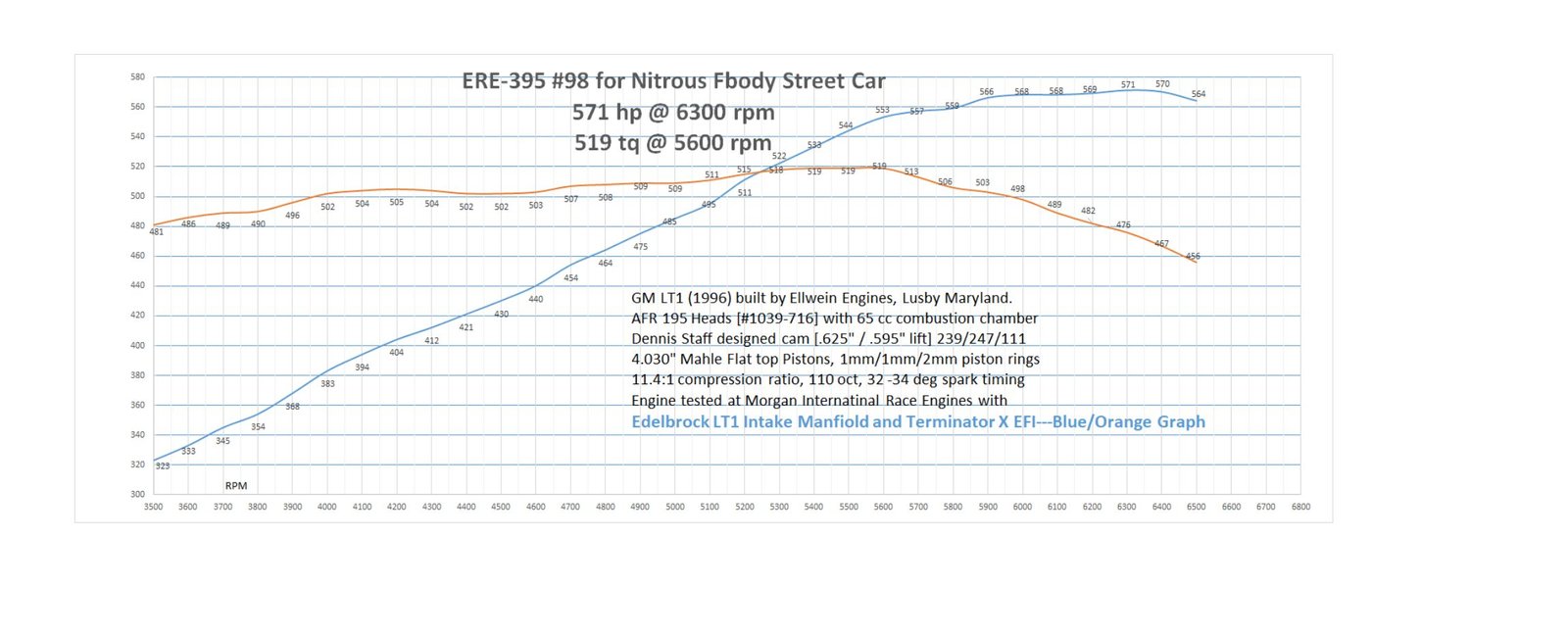
65 cc (I had written in my notes that these were 62 cc so I'm
glad I checked). The engine static compression ratio will be
11.4:1 That is using the .027" thick gasket (5.67cc)
and the 65cc chamber and 5 cc piston. |

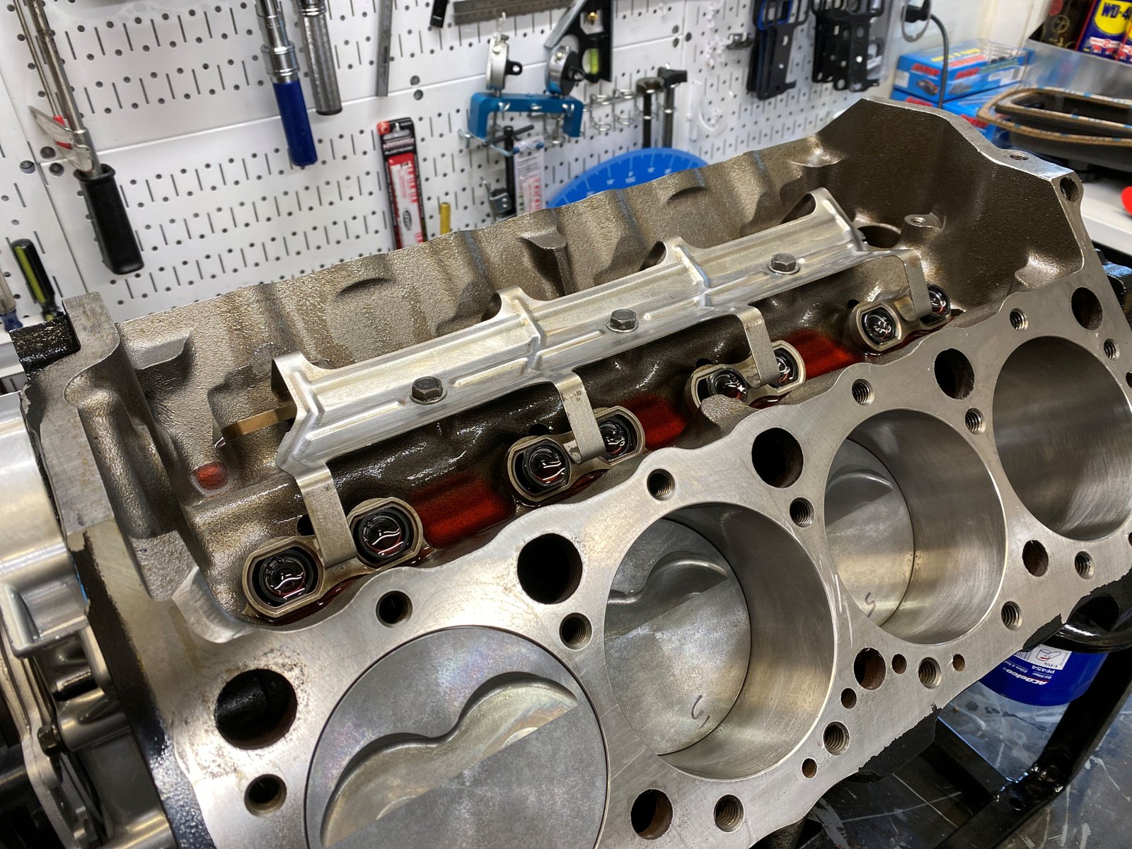
Johnson lifter installed and used and refurbished dog-bones and
lifter spider.
|

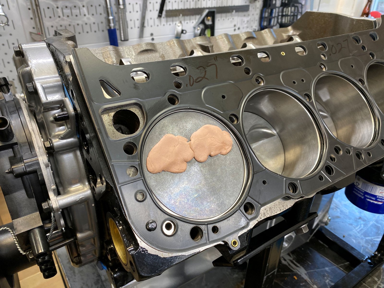
Using the Cometic .027" head gasket I will now check for
piston to valve clearance. |

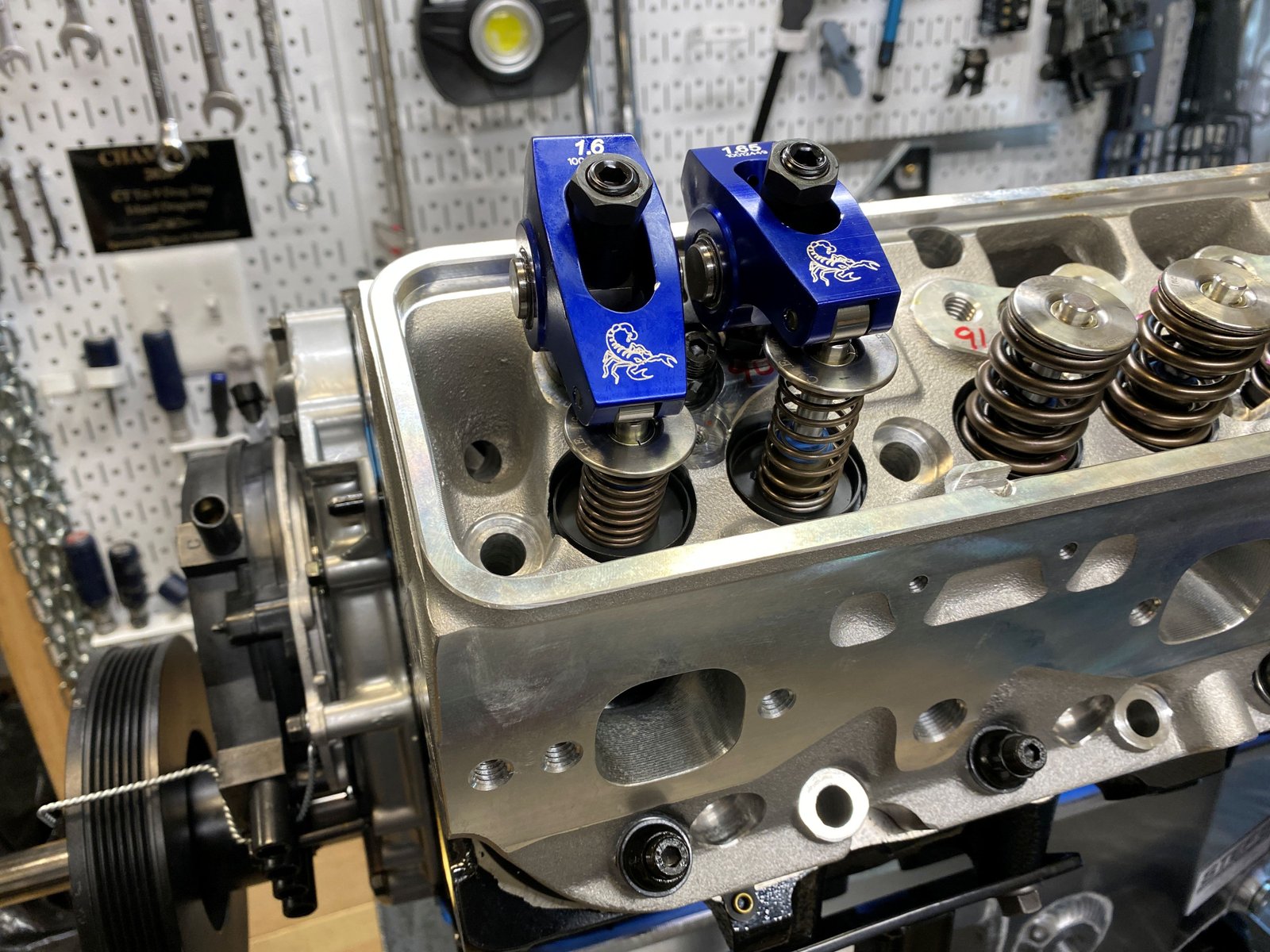
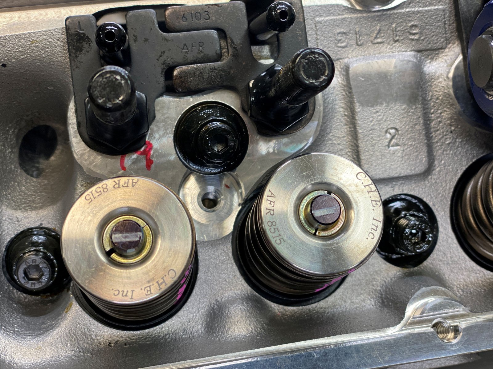
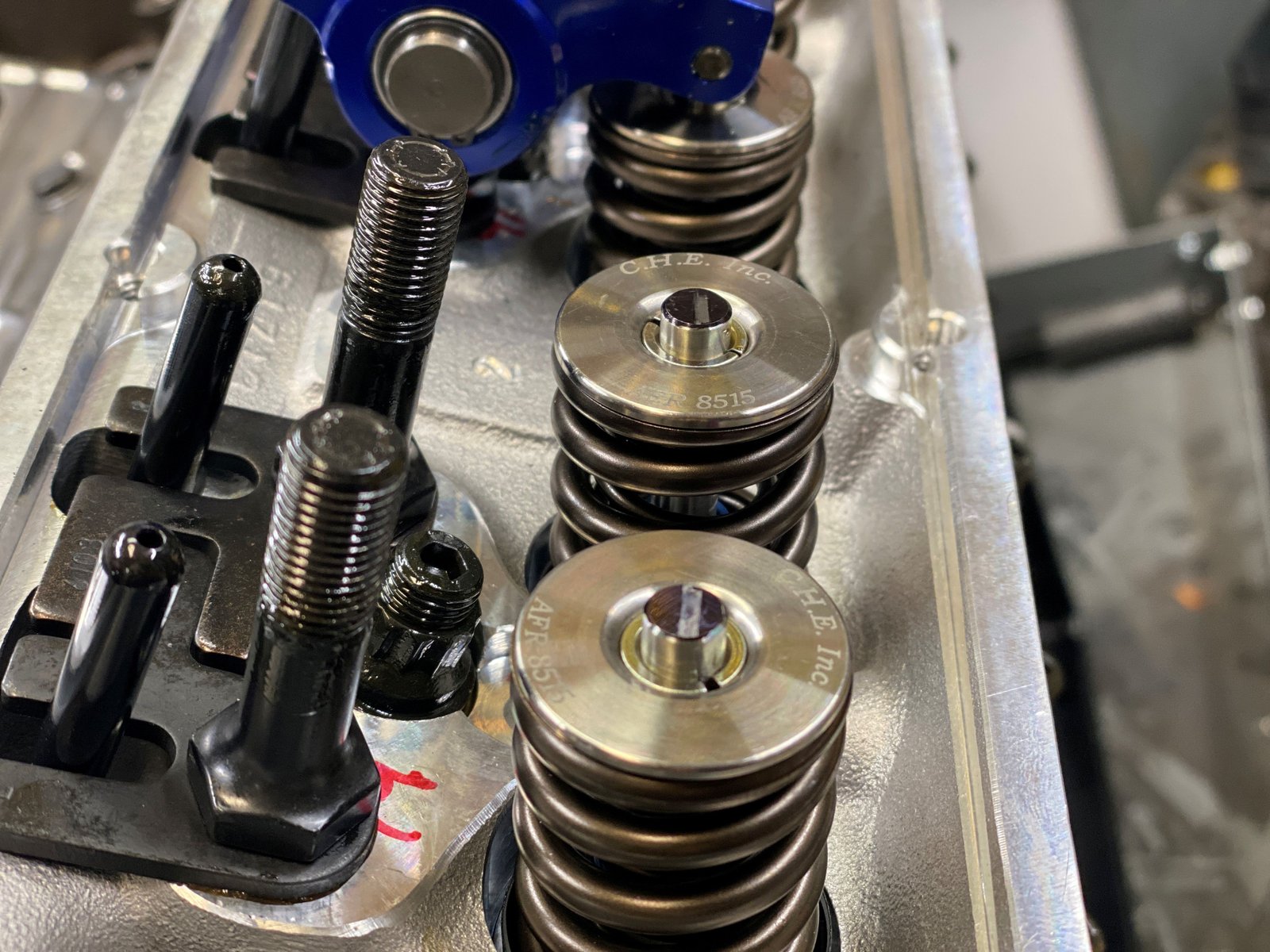
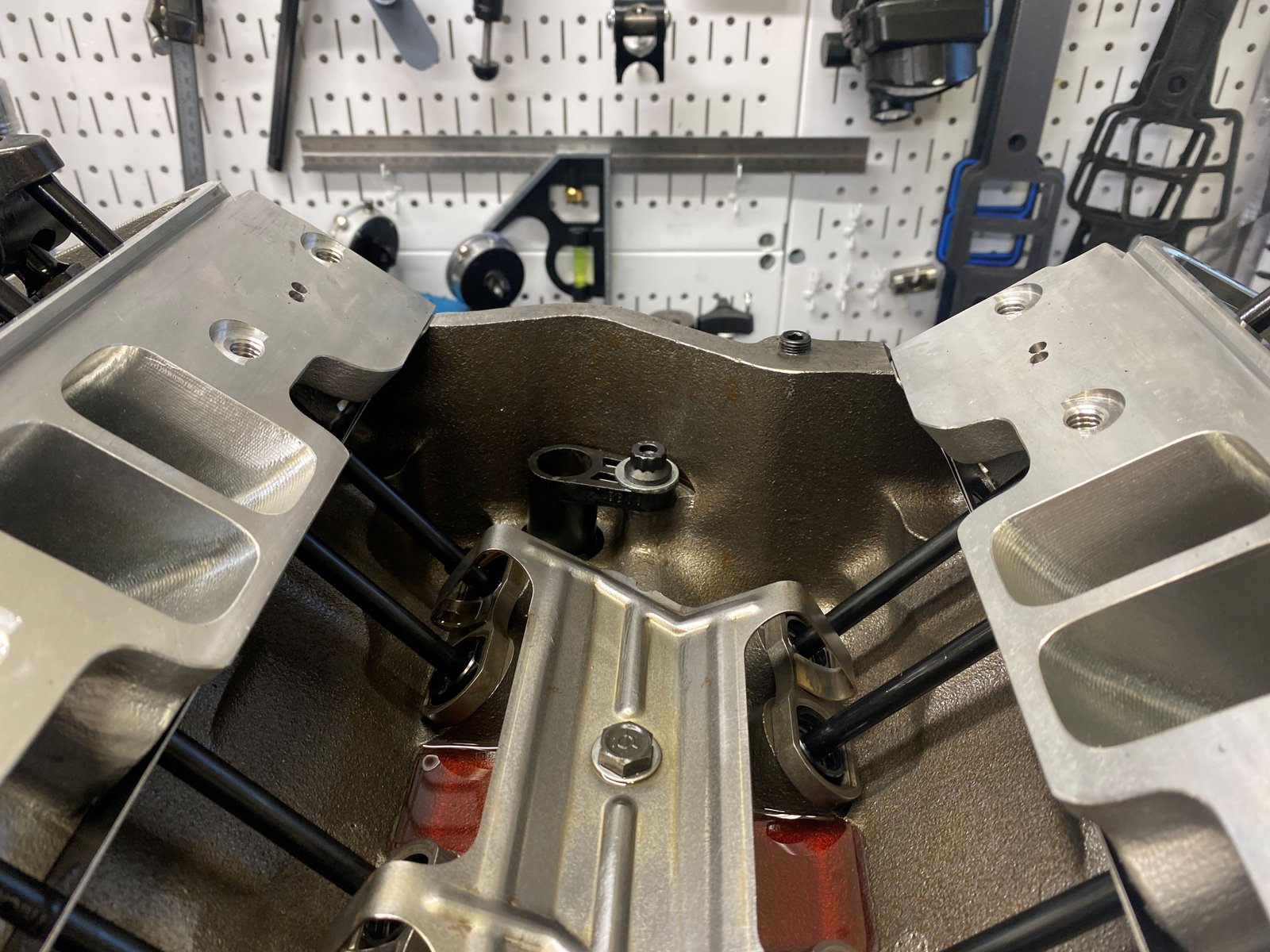
Installed checking springs and shop rockers. I don't have
the comp rockers yet.
|

Lots of clearance. Radial and lateral. |

Exhaust is .105" clearnance
|

ARP head studs ready for installation. |

Heads on with ARP studs at 80 ft-lb and the threads have RTV in
the block and high pressure grease for the 12pt nuts and washer.
|
 |

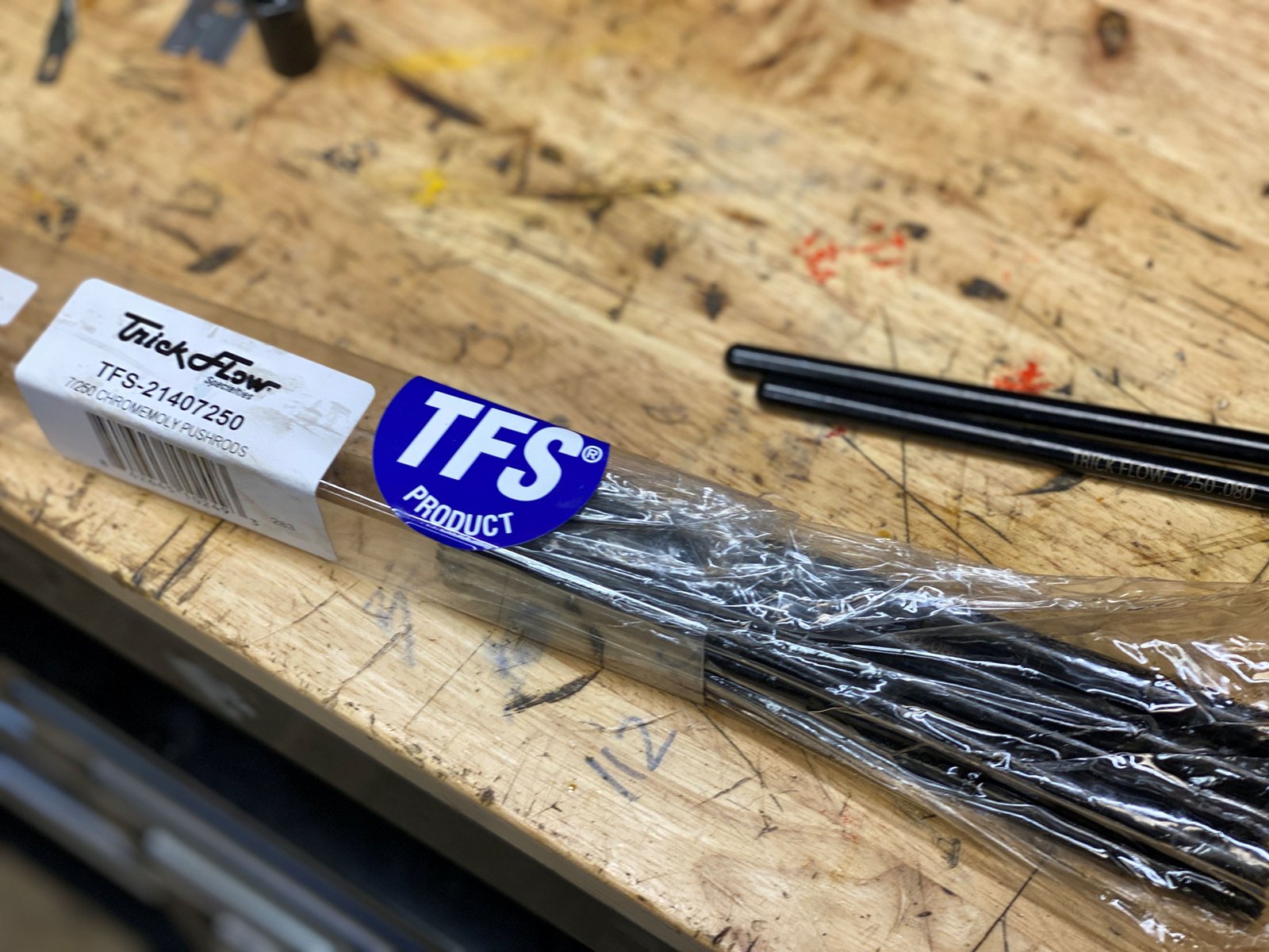
7.250" pushrods (5/16" diameter)
|

The pushrod guides are from AFR and they are adjustable.
It takes quite a while to get them in the proper position for
rocker tip to valve tip and then torqued down. |

Verified proper pushrod length.
|
 |

|

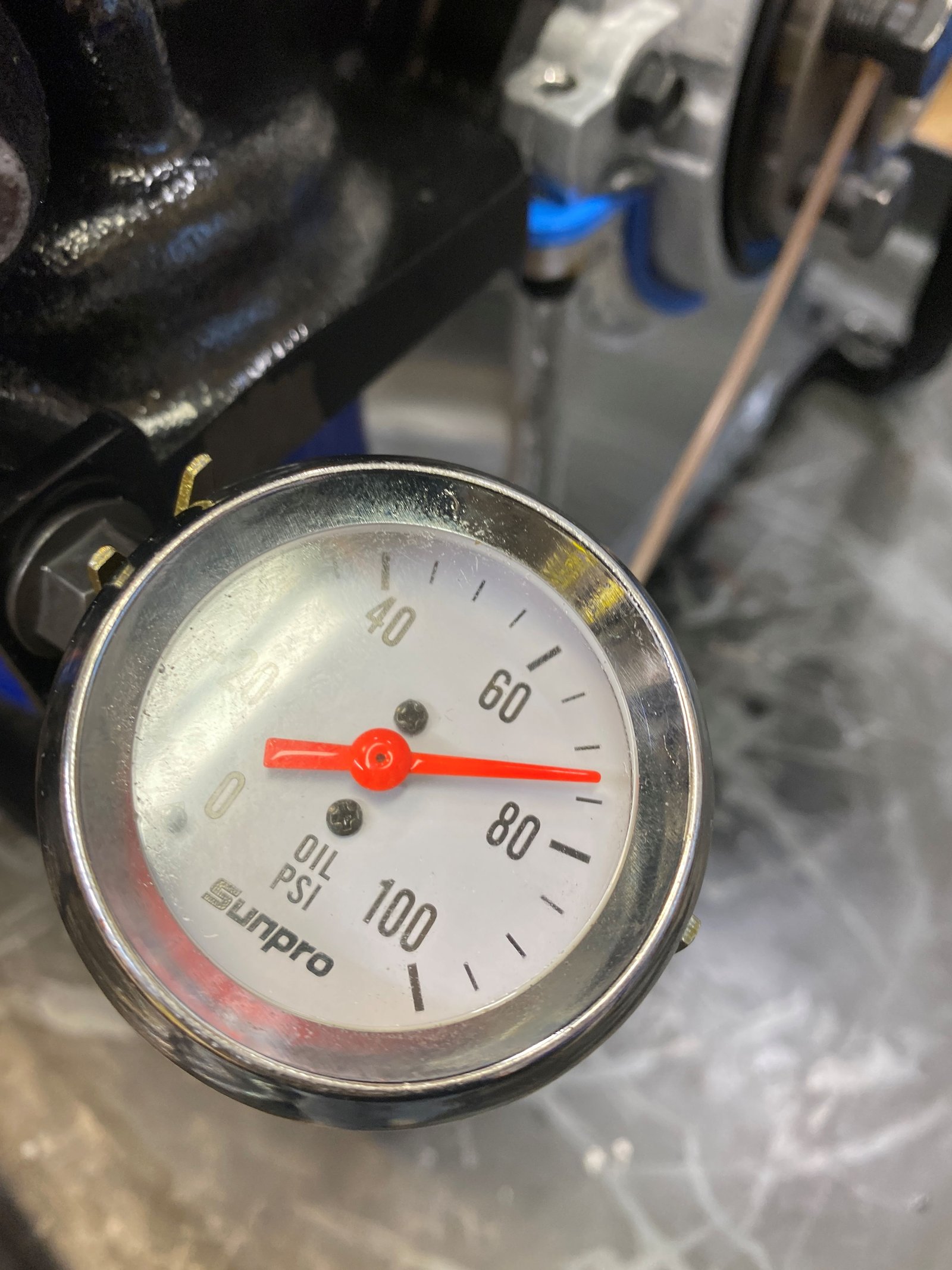
Now testing oil system. The Melling 10554ST pump is
awesome. |

|

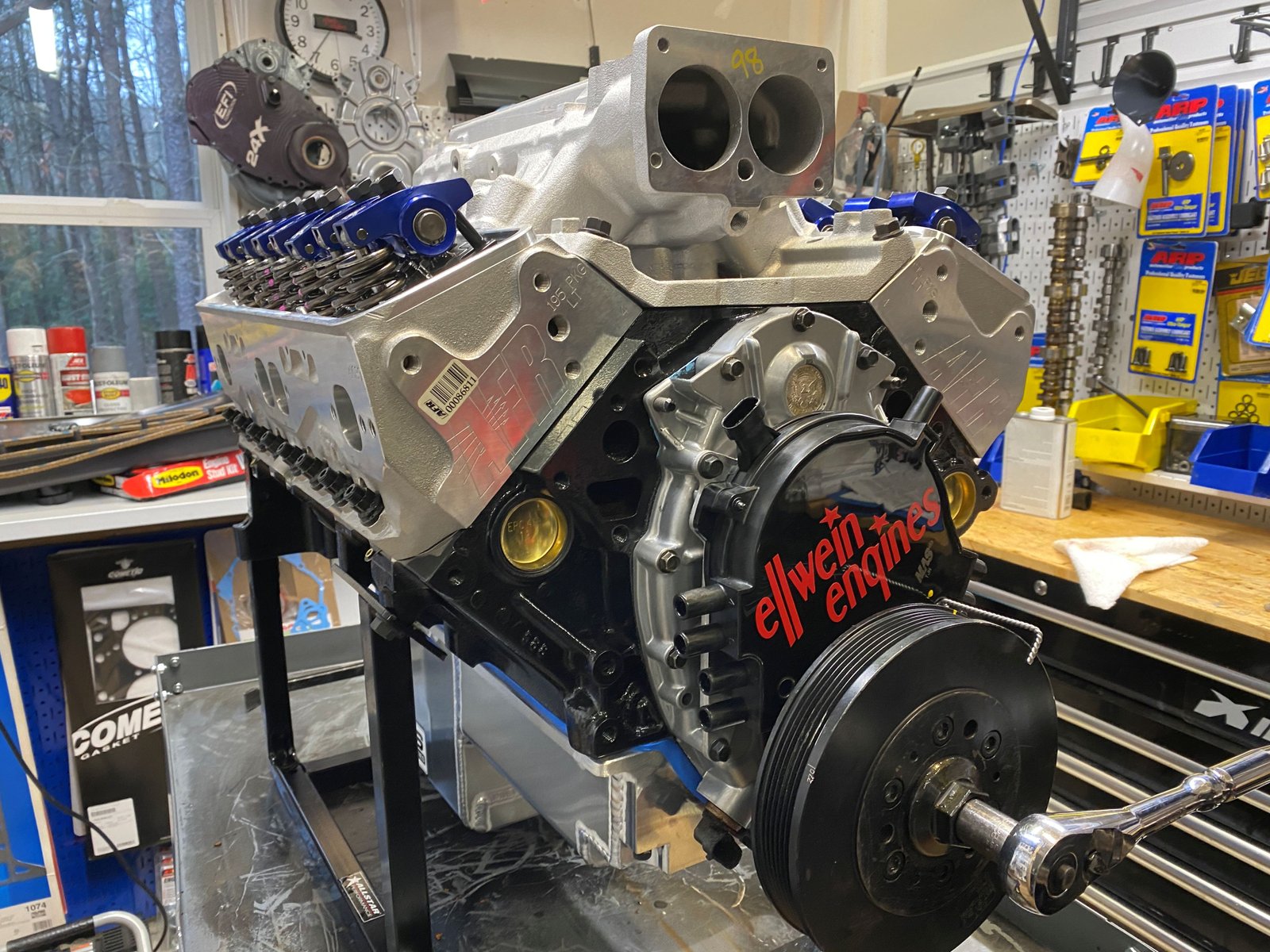
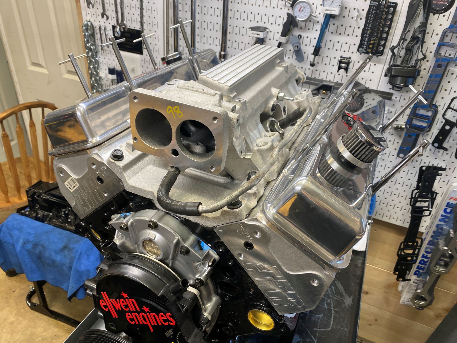
Customer provided Edelbrock LT1 intake manifold. It is
just a test fit for now. It is not RTV'ed and bolted down. |

|
 |

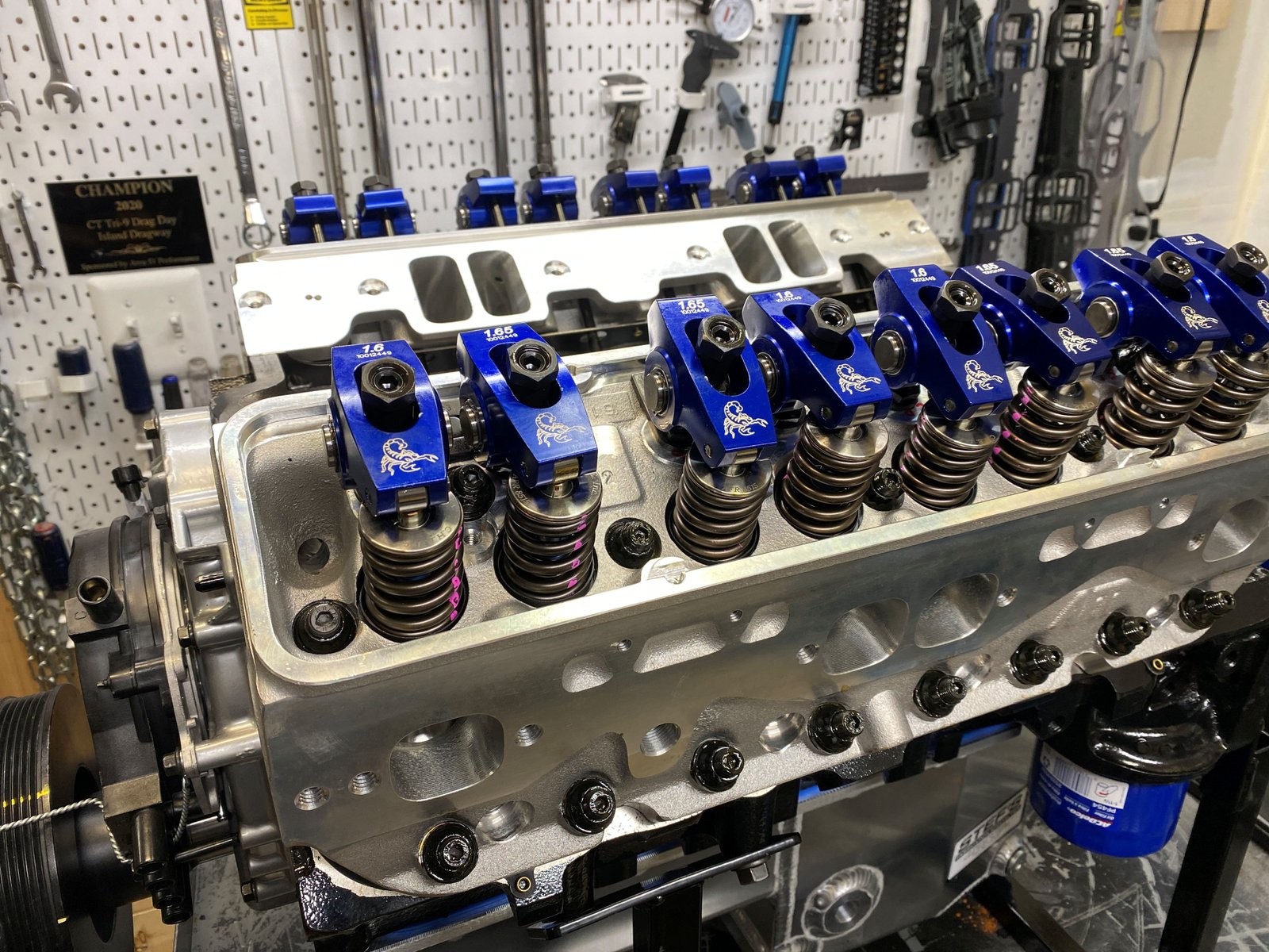
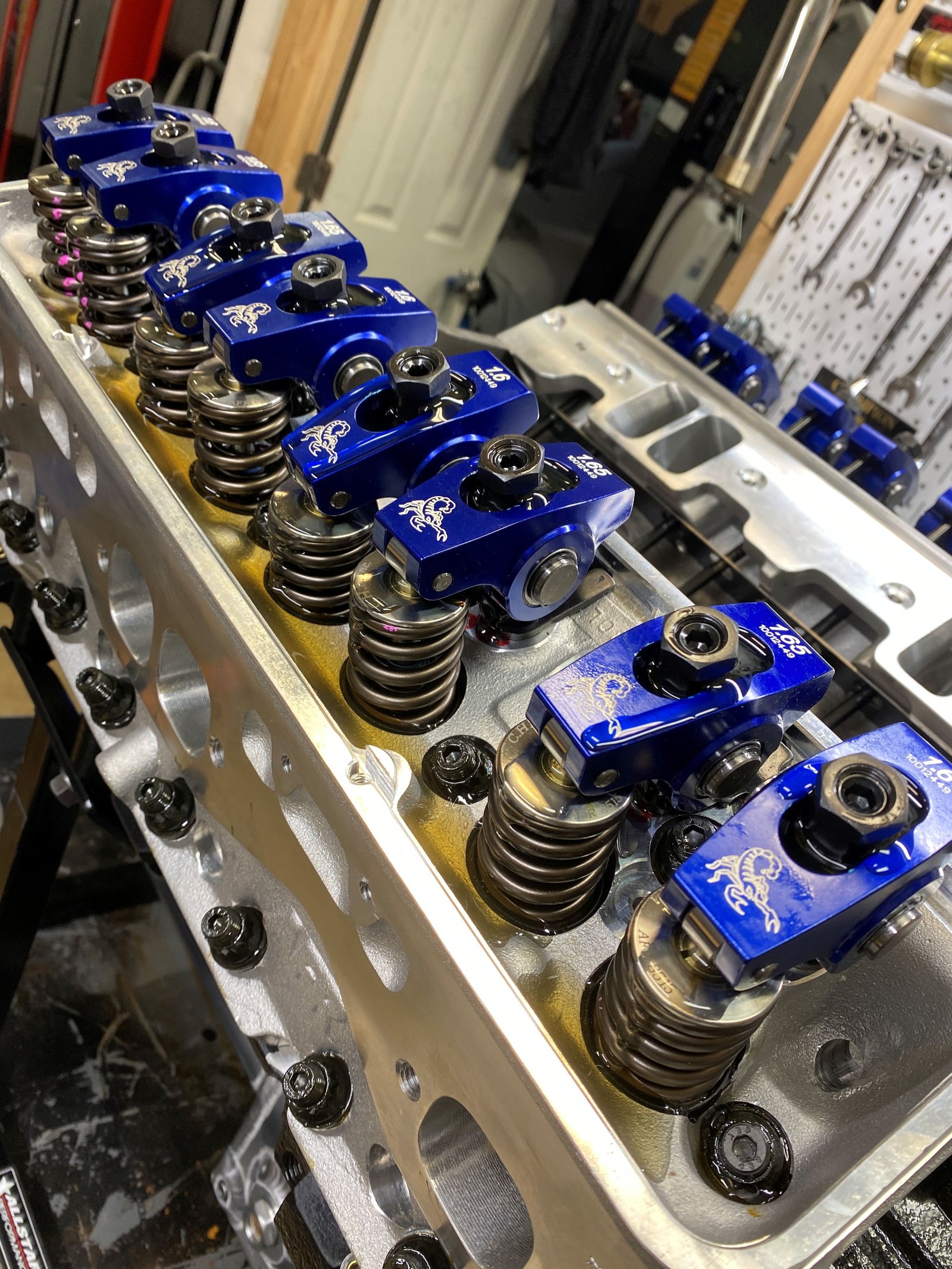
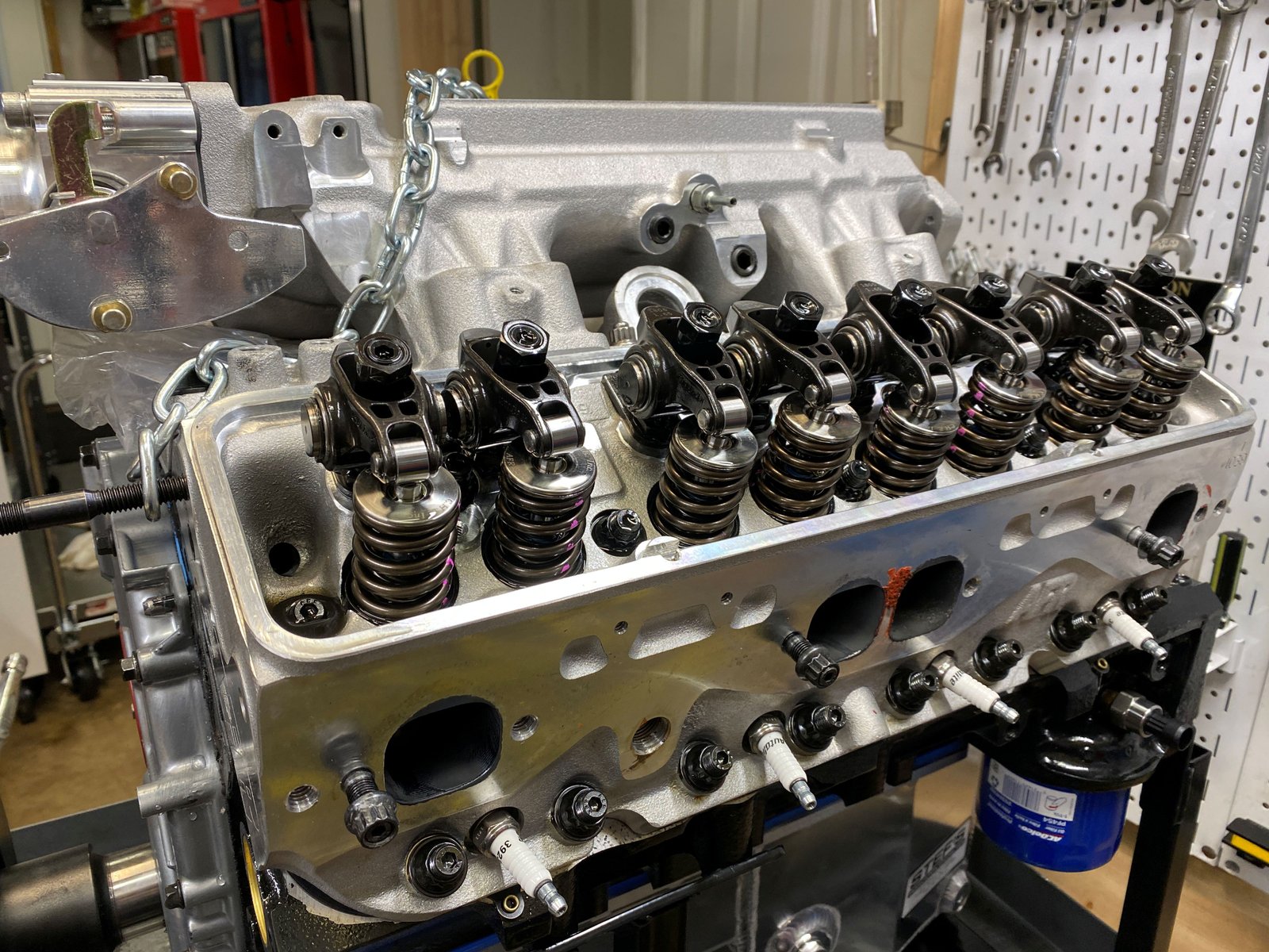
Replaced the blue roller rockers with a mixed set of Comp ultra
pro-magnum (endurance) (1.65 intake and 1.60 exhaust). This is
the test for pushrod length using the 7.250". Looks
good. My one photo of the Comp roller rockers did not turn
out. I'll get a photo of them later.
|

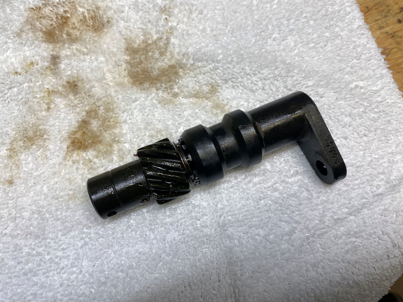
New gear on a refurbished core. |

Installed and torqued to 20 ft-lb
|

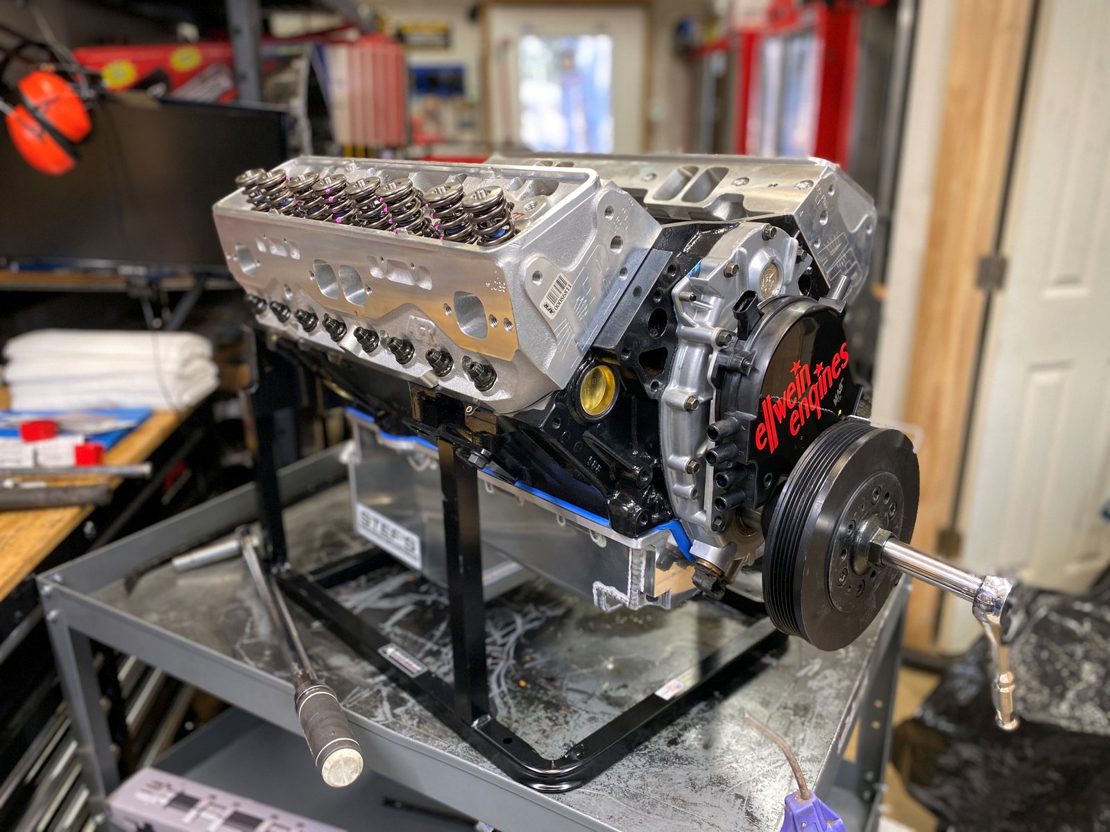
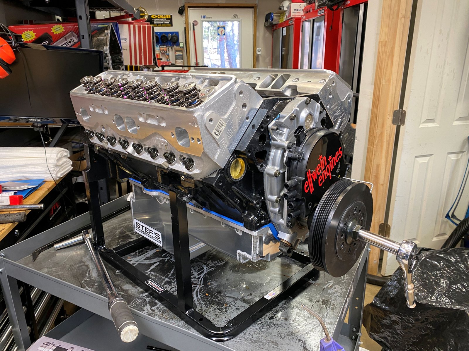
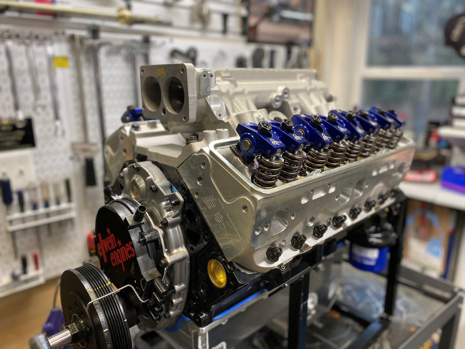
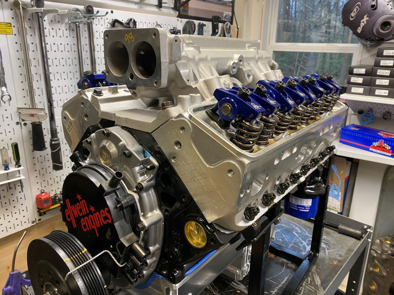
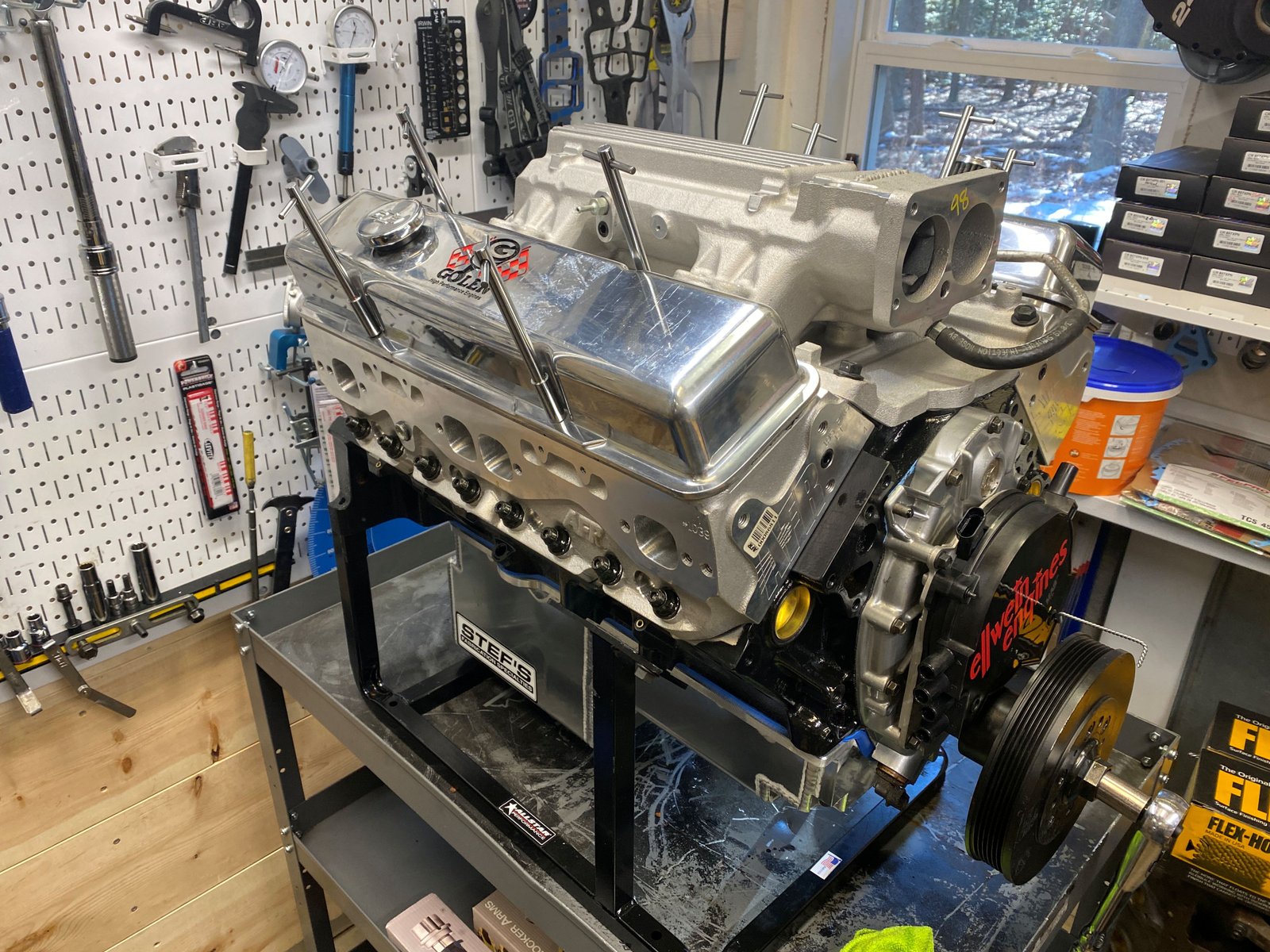
Intake manifold on. Valve covers are a dyno only set
that gives lots of internal room for roller rockers and shaft
rockers. |

|
I have a few parts on order from EFI
Connection:
Crank sensor
Cam reluctor button
Cam sensor holder and cam sensor
Dyno day target is Tuesday the 9th. |

|

Here are the parts from EFI Connection which give a 1X cam
signal so that I can run EFI on the dyno. I'll be using my
Terminator X system. |

|
 |

|
 |

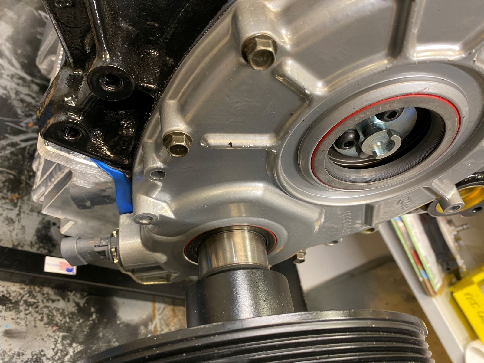
You should be able to see the crank 24X sensor at the bottom of
the 1996 timing cover.
|

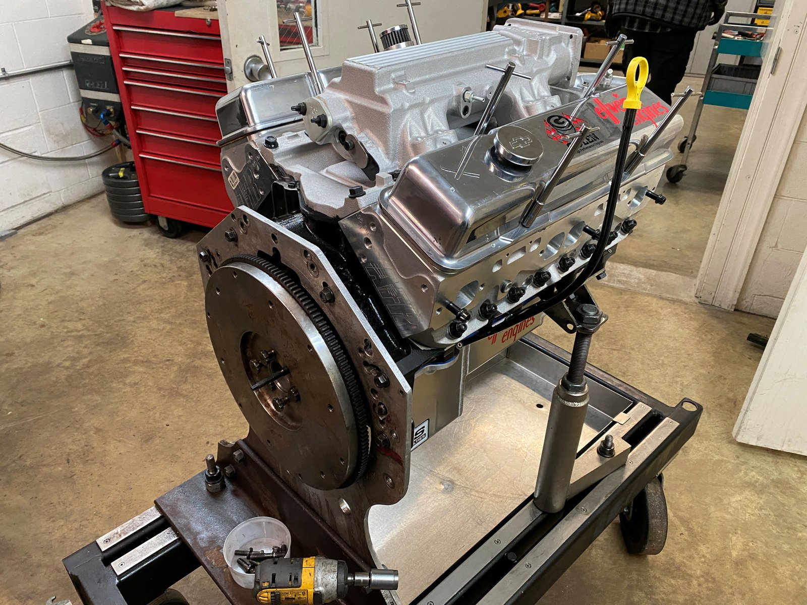
Here we are at the engine dyno. I borrowed Mike Noonan's
valve covers which had his coils. Also borrowed his
Terminator X brain box. All worked quite well. |

|

Finally: A photo of the Comp Ultra Pro
"Endurance" rocker arms. |

|

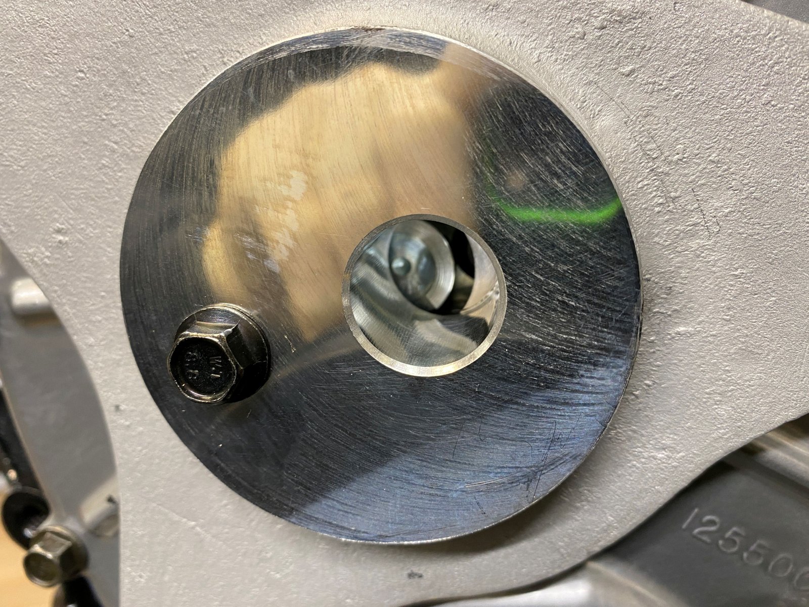
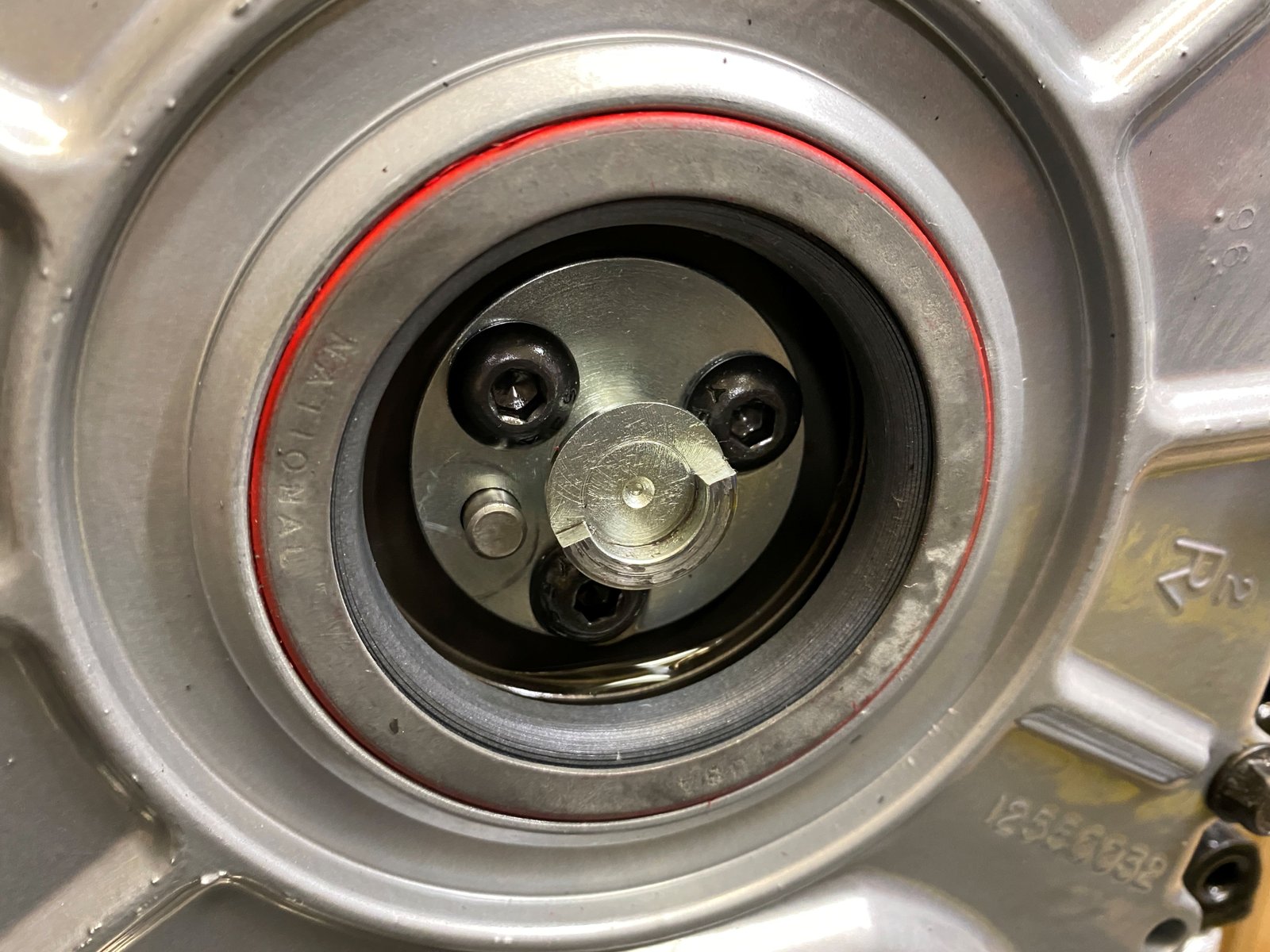
I noticed something when taking dyno parts off the engine. The
cam reluctor just slightly touched the cam sensor housing.
If this were my engine I would fix/adjust that by installing the
cam sensor housing with thin washers at the 3 mounting tabs. |

See here where there is slight witness marks from the cam
reluctor. This is the piece that takes the place of the
optispark and holds the cam sensor.
|

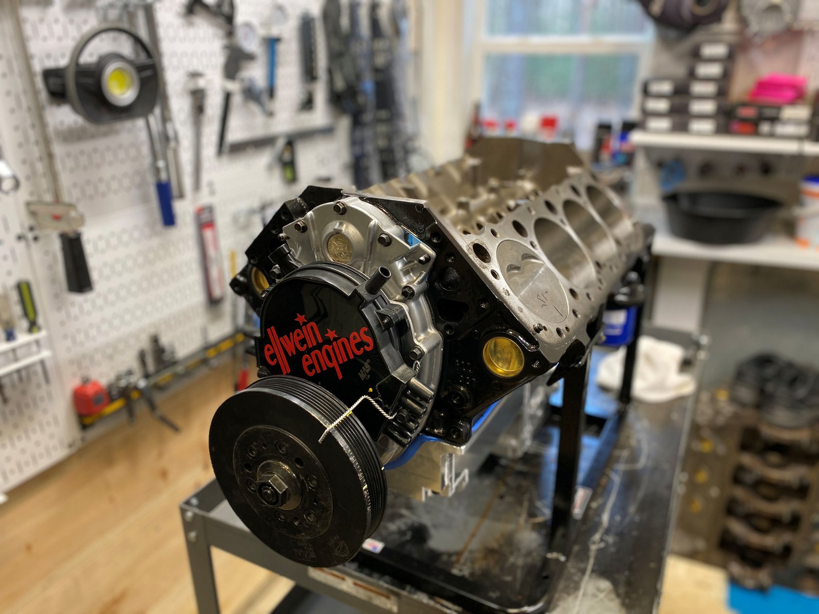
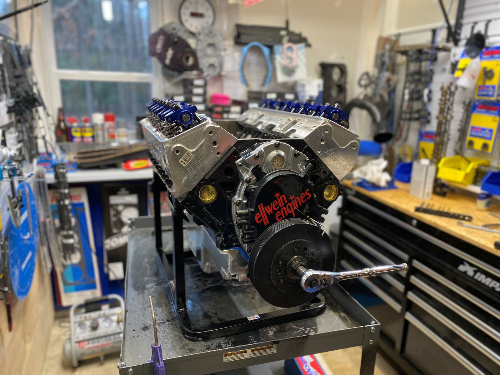
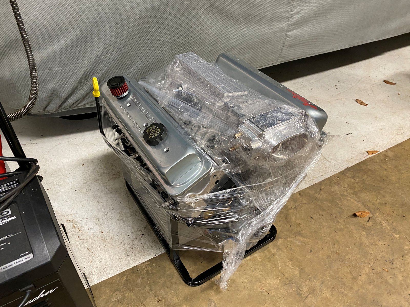
Wrapped up for now and waiting for good weather to ship.
Those are my dyno valve covers being used to keep the engine
clean. |