|

The motor as delivered. Very nice piece. ARP head
studs, Eagle splayed main caps, Callies crank and Oliver rods.
|

The motor was putting out some massive horsepower. The owner
said 600+ rear wheel HP. This is with the help of an ATI
huffer.
|
|

The valve-train was the only problem with the combo. Bent pushrods
and broken roller lifters caused some damage but nothing
major. A few dings on the crank and underside of #7
piston
|

Some left over debris.
|
|

The crank is in very nice shape and simply needs a polish.
The Thunder Racing keyed LT1 hub was dang near welded onto the
snout though. It had to be machined off. I think the
hub should have been honed a bit to fit onto the Callies crank
snout.
|

The SRP piston looks to have held up quite well. The Total
Seal rings are part number MS3690-35 The most expensive set
of rings known to man. The top ring is designed for severe
nitrous and blower applications.
|
|

I sent the block off to Brinkley Auto Machine for a health check
and cylinder hone. No cracks detected. Very good and
square deck. Mains OK. Cylinder hone complete.
|

I cleaned the block after Brinkley finished his work. Hmmm,
that rust needs some engine black paint.
|
|

How's that?
|

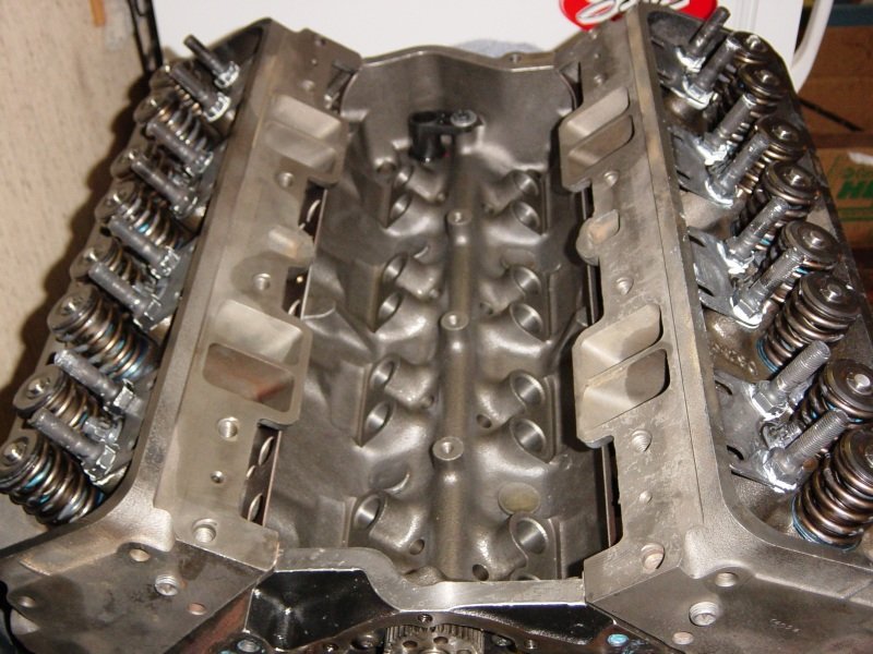
Block is in my shop, clean and dry and oiled. I use the same
cam bearings that the original builder had in this block,
(Dura-Bond). I measured all the cylinder bores (without the
heads on) and they were round and at 4.0295".
|
|

I need to measure the crank for bearing size. The original
builder used
Clevite H-series bearings. (one bearing half standard and one
bearing half .001 under for the mains and rods). That was an
excellent choice. The crank measures 2.4480" on all the
main journals and 2.0990" on the rods. The rods
certainly need .001" under bearings.
|

I'll order a few sets of Clevite H-bearings, Standard, .001"
Then get this thing up and running.
Also have the Total Seal rings on order and hopefully a custom cam
from A.I.
|
|

Now in order to spec out a custom cam, (from Advanced Induction),
I need to know the engine combo specs. The heads cc to 62cc
and the pistons are 24cc D-dish so static compression ratio is
around 9.3:1
|

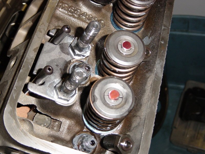
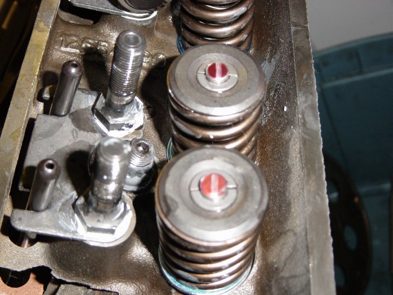
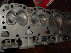
Here are the heads after refurbishment by Brinkley Auto Machine in
Forestville MD. Brinkley did a valve job and installed the
valve springs to the exact specs on the CompCams box, (spring
#978-16, 403lb/in spring rate, installed at 1.850" for 126lb
seat).
|
|

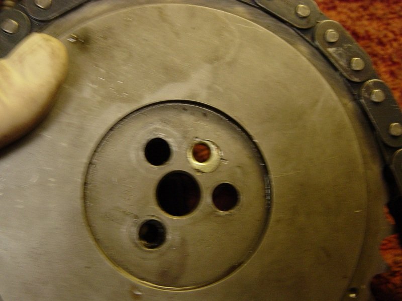
This is the GM extreme LT4 crank sprocket damaged by heat when
taking off the hub. A new sprocket can be purchased separate
from DAL for $46 bucks. Part number 14088784.
|

If possible, I always install the crank sprocket when the crank is
out of the block. It's just easier. I do have a very
nice hub installer that will press that thing on like a knife
through hot butter but it's on now and should never have to come
off.
|
|

Now this is the 1st step in measuring for main bearing
clearance...having a clean and ready block. The original
builder used a mix of std. and .001" Clevite H-series
bearings which is exactly what I'm going to use. They didn't
just slap this thing together. It was assembled very well
with great care. Let me show you some of those nice
details.....(next thumb)
|

The oil passage opening to the main-thrust bearing is modified to
allow oil a direct shot to the Clevite bearing oil hole.
Nice touch. I'm now doing that with all of my motors.
|
|

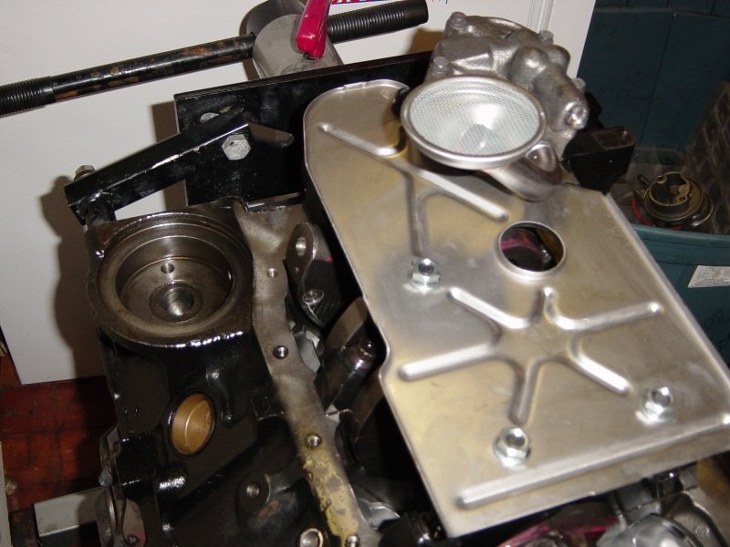
I started out by swapping out 3 of the ARP main studs with the
longer windage tray Milodon studs. This allows for use of
the stock windage tray and that tray is essential for good oil
pressure. You guys who say your oil pump sucked the pan dry
probably and actually had aerated oil, (if you didn't have a good
windage control system).
|

So I started out with .001 bearings in top and bottom and then all
caps are torqued to spec. The crank main journals are all
2.4480" so that's what you subtract the bearing dial bore
gauge readings from. #1 was 2.4498, #2=2.4496,
#3=2.4497, #4 not measured and #5 was 2.5000. I
already know that's a bit too tight so I didn't even measure
#4. Those readings give the following
clearances---.0018, .0016, .0017, #4 not measured, #5
.0020". So I did the same thing only this time with
.001 and standard bearing shells in each position accept #1.
I kept the .001/.001 bearings shells in #1. Final
clearances, #1=.0018, #2=.0020, #3=.0020, #4=.0020,
#5=.0026
|
|

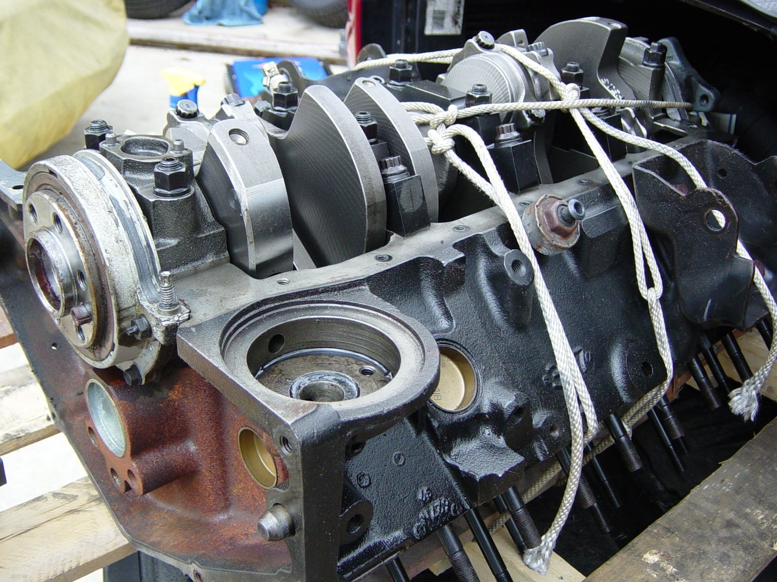
Now I set the crank in place and torqued all the caps accept the
thrust. This is where you make the 2 thrust bearing caps
share the load. You see what thrust is without the bottom
cap, (.008"), then torque the bottom cap and hope that it is
close to the same, (.008"). If you get .005 or so
then the 2 thrust shells are not sharing the thrust equally.
You just de-torque and try again if that is the case. The
crank end-play final is .008" which is a bit on the high side
but the fix is regrinding the crank. I think .008" will
be ok.
|

The crankshaft is in for good. Now onward to measuring rod
bearing clearance. I can do that to get ahead of the
game. But that's as far as I can go. Total Seal rings
are the hold up. I ordered them more than a week ago and
still do not have them in hand. As soon as I get the rings
and also the Ai custom cam this motor will be finished.
|
|

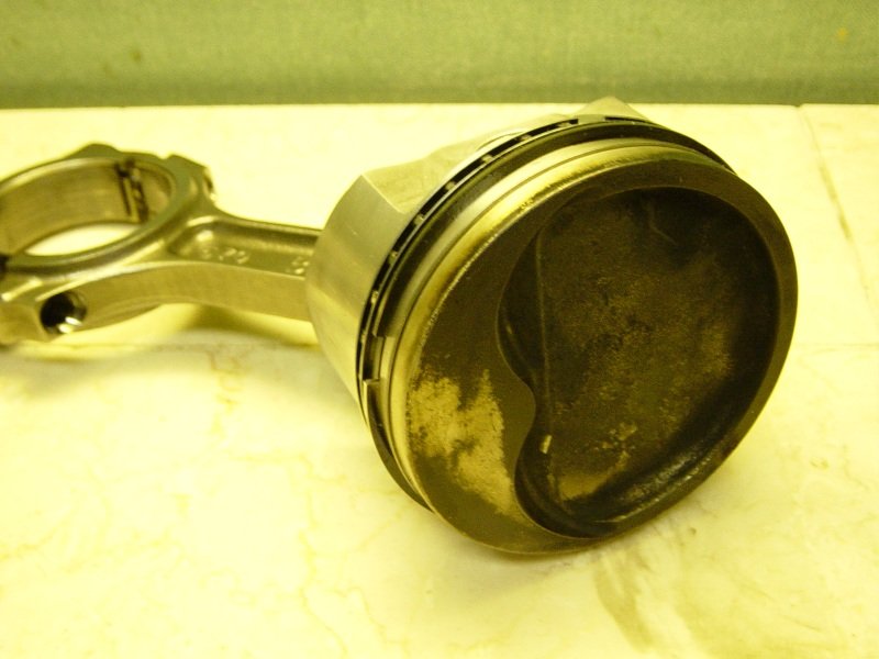
Piston #7 is the only piston that was damaged by debris.
These gouges on the edge are deep but pistons can live in a strong
engine with things like this. I'll buff the gouges a bit.
|

Really cannot take the gouges out or a lot of material will be
removed. I buffed the area just to make things smooth.
|
|

So now it's time to measure all 8 rods for bearing
clearance. To do all 8 rods takes me hours. It
requires inserting the bearing, torquing to spec, measuring the
rod with a bore gauge and subtracting the crank rod journal measurement
from that. Also need to clean the rods and pistons and goop
up the bolts with Oliver thread lube. These 7/16"
Oliver/ARP WSB bolts require .0053" to .0058" stretch
which should be achieved by 30ft-lb then 40deg.
|

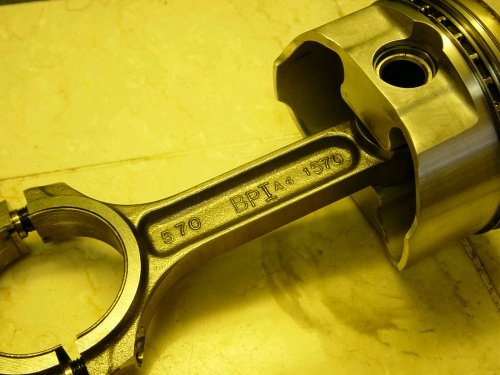
I'm using the same bearing sizes that were in the rods.
Standard and .001 mix. These are Oliver forged 5.7" rods and
are very high quality. They are not the "billet"
rod but they are damn good rods.
|
|

Put the bearings in, torque to 30ft-lb, turn the bolt another
40deg. That is a lot of torque. At amounts to around
90ft-lb. I'm not using the torque wrench to crank the bolts
40deg. but I eye-ball it with this breaker bar.
|

Then check the bolt stretch. I get .005 to .006"
|
|

Now we bore-gauge it and come up with .0018 to .0023" between
all the rods #1 through #8. That is very good.
|

All rod/piston combos ready for rings and ready for installation
into motor. Hey Total Seal! Where are my rings!?
|
|

May 9th: The Total Seal ring set arrived. Part number
MS3690 35, (gapless top ring, advanced profile, napier 2nd
ring. $300+ bucks for these rings. This is the top
ring combination (upside-down).
|

Here is how the top ring combo would go into the piston.
|
|

Here is a Napier 2nd ring. The Napier has a little scraper
lip. The top and 2nd rings still need to be file fit.
To give me an idea of what to gap them at I put the old rings in
the bore and measured what gap was used previous. They had
.034 top and .030 2nd. I'm going to duplicate that.
|

All rings filed and stored in their bore.
|
|

Now to install the rings onto the pistons. The top gapless
ring, (which was gapped at .034") goes on first.
|

Then the thin ring goes under the thicker ring. The thin
ring looks very much like an oil ring. Total Seal has a nice
warning tag on these thin top rings. "Warning, these
are not oil rings---don't mix them up" or some such
words.
|
|

All rings on. Pistons stored in order.
|

All piston/rod combos installed.
|
|

Just wanted to show you the oil pump drive. It's a nice
bronze gear. The original engine builder did a top-notch
job. Many nice little details were put into this motor.
|

Another neat touch from the original build is tapping the front of
the 3 oil galleys. The local machine shop, Brinkley Auto
Machine does the same thing.
|
|

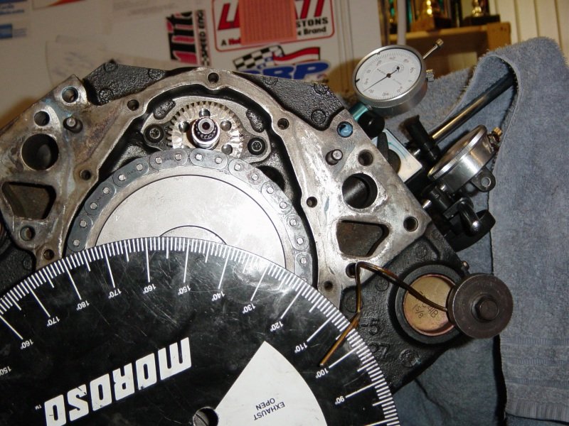
Now I have David's LT4 extreme duty timing set installed and this
photo shows TDC during cam-degree set up.
|

I've run into a big snag. The cam degrees around 8 deg
advanced for both intake and exhaust lobes. It's cause could
be the cam but more likely it's due to the timing set or crank
nose/sprocket key. This photo shows me pressing on a
different timing set. I'll degree the cam again with this
timing set.
|
|

It still comes in 8 deg advanced.
|

I tried numerous other crank/cam timing sprocket combos and still
no luck. Now this photo shows me pulling the cam. I am
going to stick another cam in and see if the timing is still
messed up. (to rule the cam in or out as the cause).
|
|

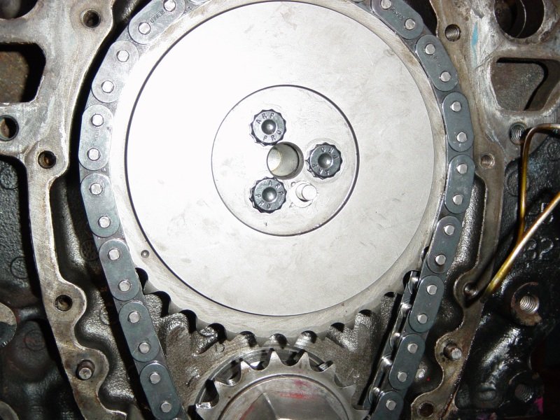
It's still off even with a known good cam. So I stick
David's new Ai cam back in and I use Cloyes double roller crank
sprocket at 4 deg retarded and also this Hex-Adjust cam sprocket
set at "zero". The cam then degreed very good,
(107 ICL when the cam card calls for 106).
|
I'm stuck
for now. I'm sure David wants to keep his stock water pump
so I need to get the GM extreme timing set to work. I'll
pull this Cloyes double roller set and re-install the GM extreme
set and try out different cam gear pin retard
bushings. |
|

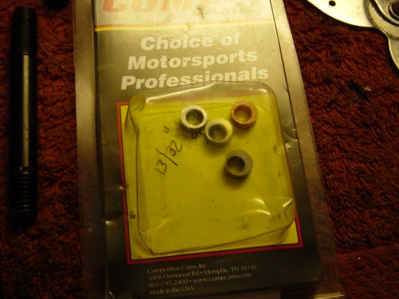
OK, here is what was in the
timing set. . . a cam pin off-set dowel pin bushing. This
looks like a 2 deg. bushing.
|

I have a set of them in my spare parts drawer.
|
|

I installed what looked like a 6 deg. bushing and set it
"retarded".
|

After trying all the different bushings and re-checking timing
about 30 times...I settled back on the 6 deg bushing that was
first selected. The cam card says 106 intake centerline and
I get 105 deg. That is very close and as close as I can get.
|
|
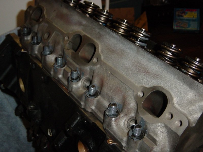
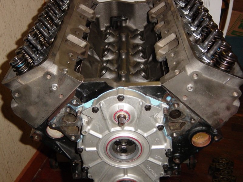
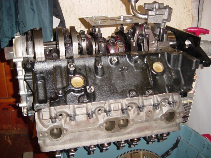
Now cleaned the head deck surface to get ready to install and
torque them to spec.
|

This motor uses head studs which are very good for blower motors.
|
|

Both heads on and torqued and rocker studs and guide plates on.
|

And the timing cover with new seals.
|
|

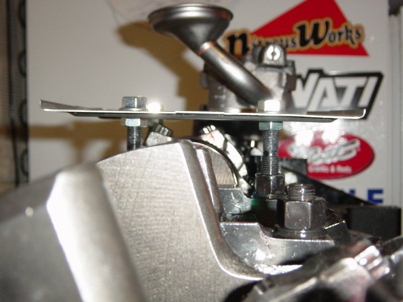
While we wait for GMPP LS7 race lifters, I can at least check that
the pushrods are the right (or wrong) length. Magic marker
the valve tips.
|

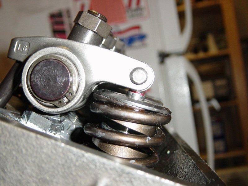
Install rockers and give 1/2 turn pre-load.
|
|

Very happy here!. Perfect geometry. I actually colored
the witness mark with silver magic marker so that the camera could
see but that's where the mark was made.
|
Now
as soon as the hydraulic lifters arrive from Scoggin-Dickey this
motor is 100% finished, (although I still need to install an ATI
damper and button up a few other things such as the rear main
seal). |
|

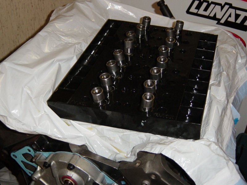
The lifters arrived from Dal. These
are the new "race" LS7 hydraulic lifters. They
soak in 30w oil overnight.
|

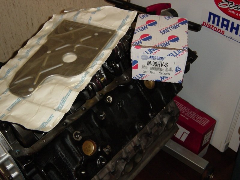
Here is my favorite oiling set up for a stock oil pan LT1.
The stock windage tray and the high volume, high pressure big
block Chevy M99HVS oil pump.
|
|

To fit around the big body oil pump you have to take tin snips to
the windage tray. I grind and wire-wheel the trimmed area to
make sure small slivers don't fall into the oil pan later.
|

This tray won't clear the rods on a stroker motor unless you use
the longer Milodon main studs.
|
|

Sometimes you have to bend the tray up and away from the rod
bolts. In this case I did not have to do that.
|

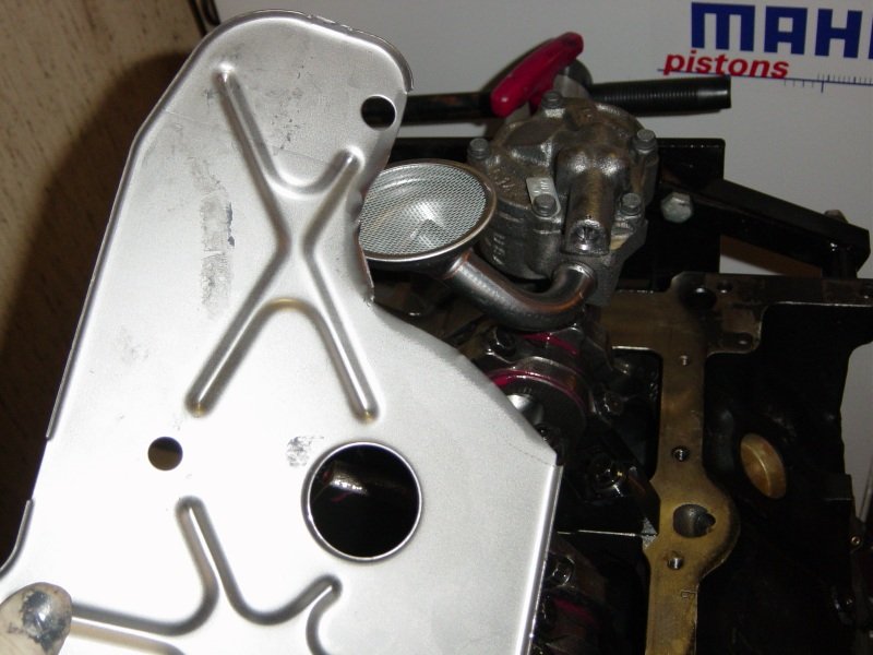
That M99HVS oil pump comes with the drive shaft and the press-on
pickup.
|