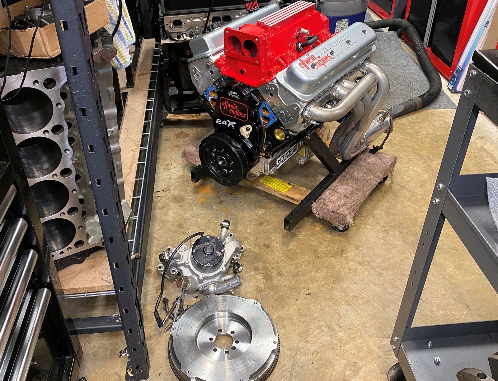
ERE-383 for EFI Connection
4-Bolt Splayed cap 383 for Fbody street car.
AFR 195 LT4 Heads, Eagle forged Crank, Compstar rods, Mahle -5cc Pistons
One of these are assigned to Mike Noonan (the EFI Connection
ERE-383).
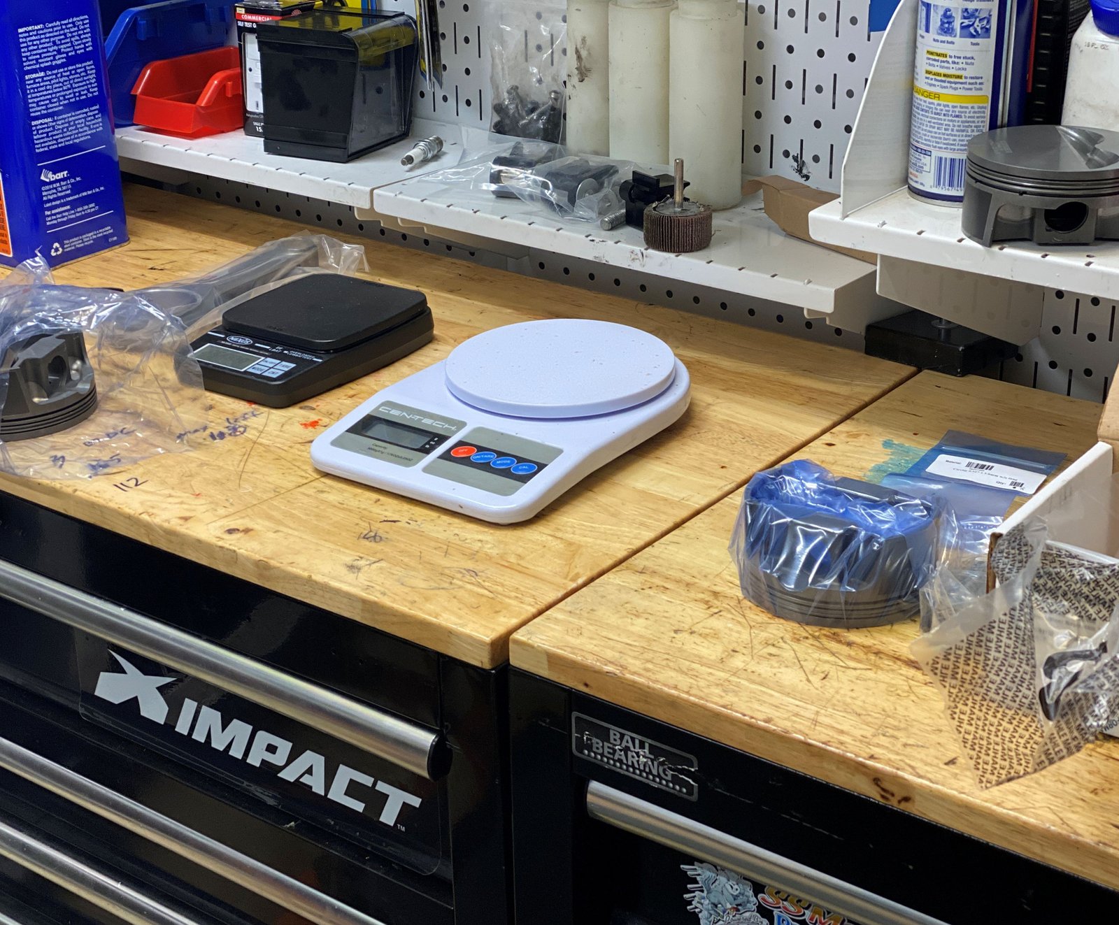
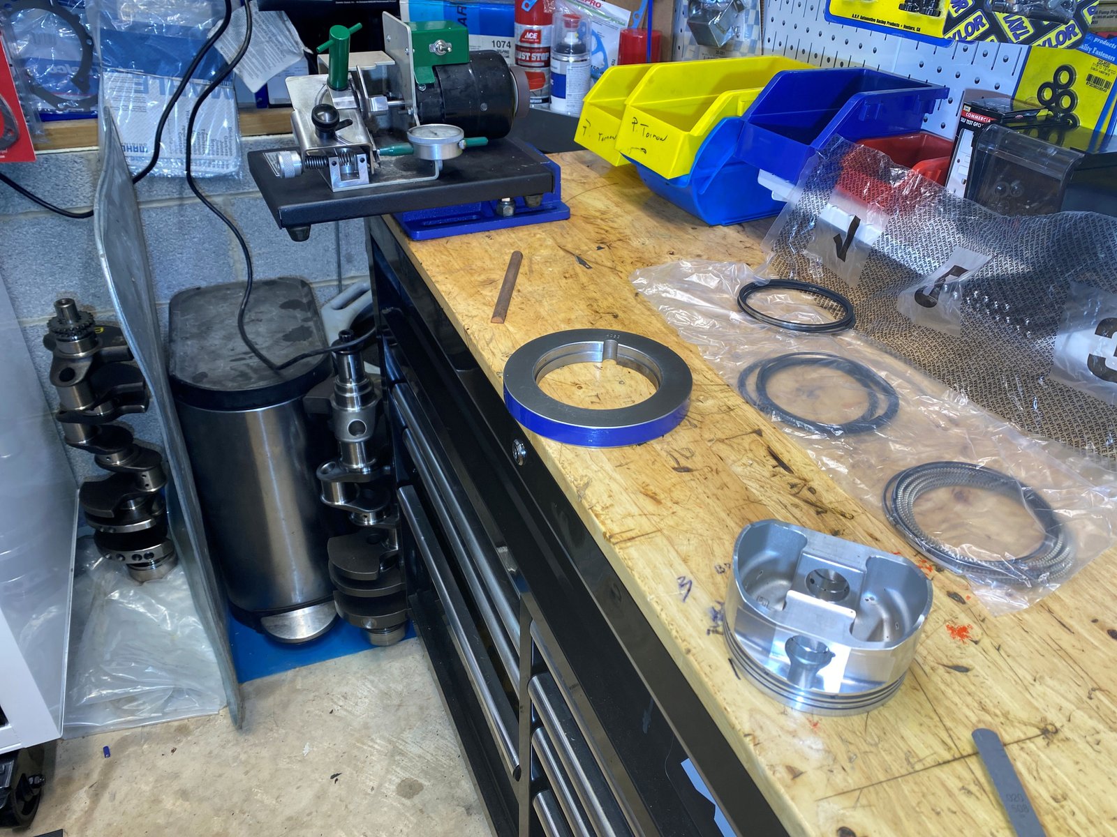
For some reason this is the only photo I salvaged of the
balance parts. Mahle flat top 383 pistons #930200630 with
the 1mm ring pack. The best piston value for the money.
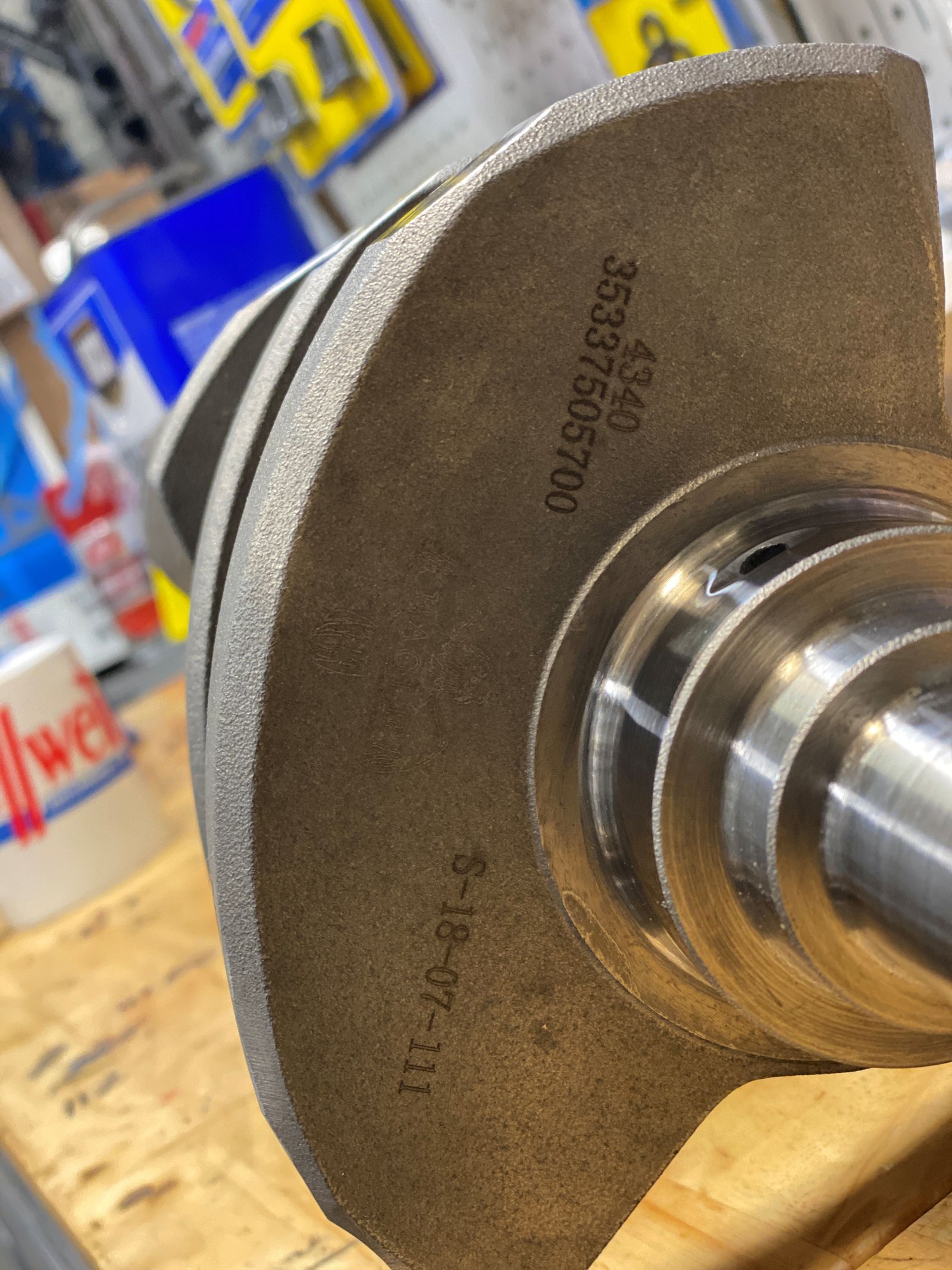
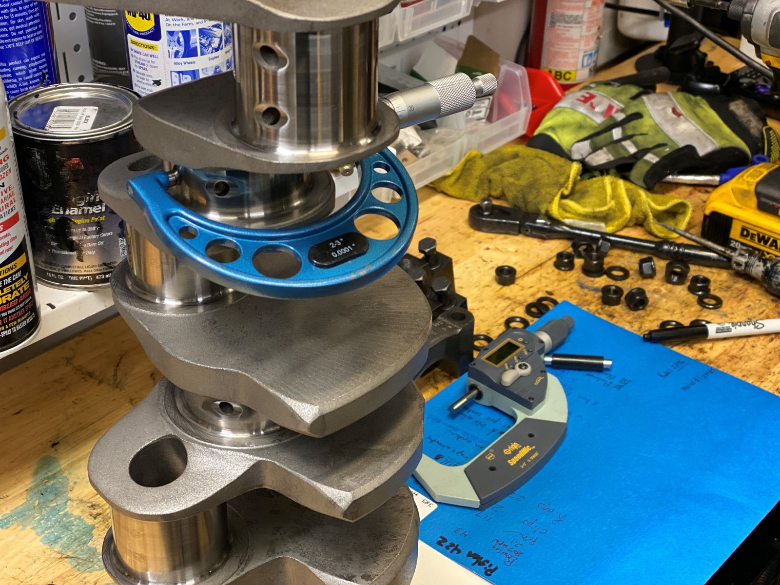
383 crankshaft from Eagle. I send it off to Clinton
Machine for balance and journal polish even though it's brand new.
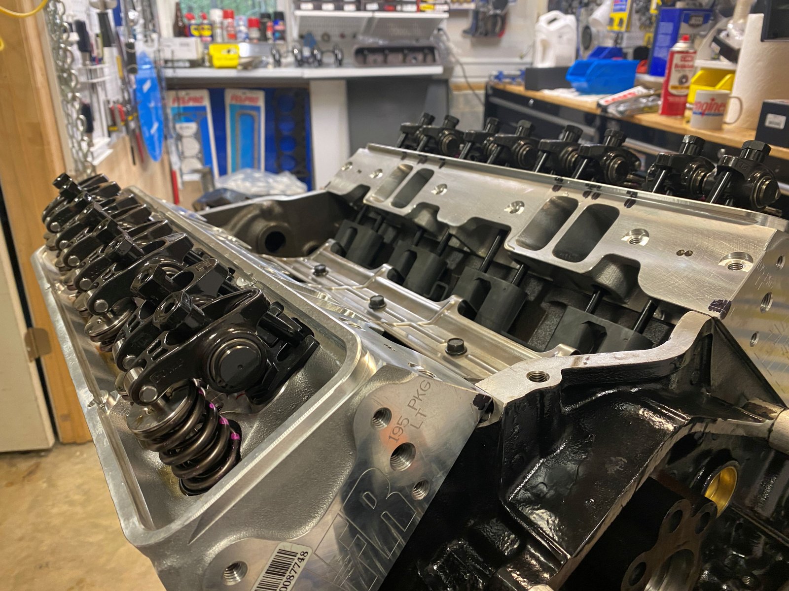
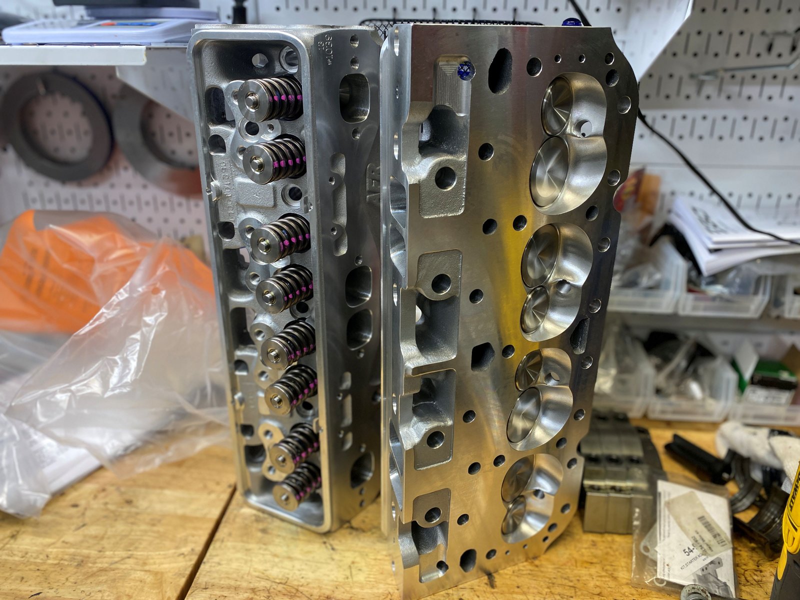
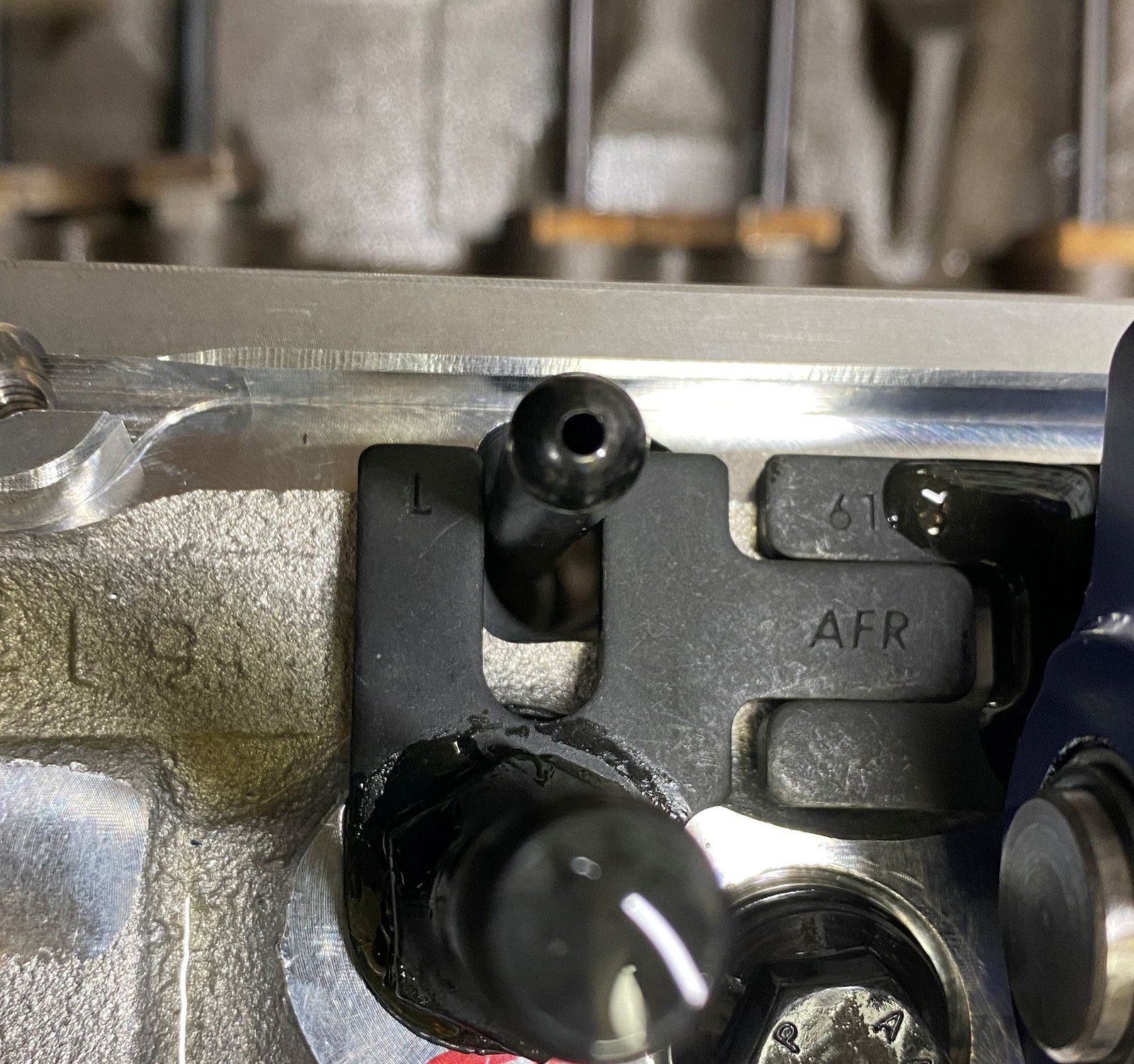
AFR heads #1039-716 with the 7 degree steel retainer upgrade.
I ordered milling to 62cc but they did not do that. The
heads are at 65cc. They did include my requested spring
upgrade. The heads have the PAC 1.270"OD spring good
for .650" lift and 7000 rpm hydraulic roller.
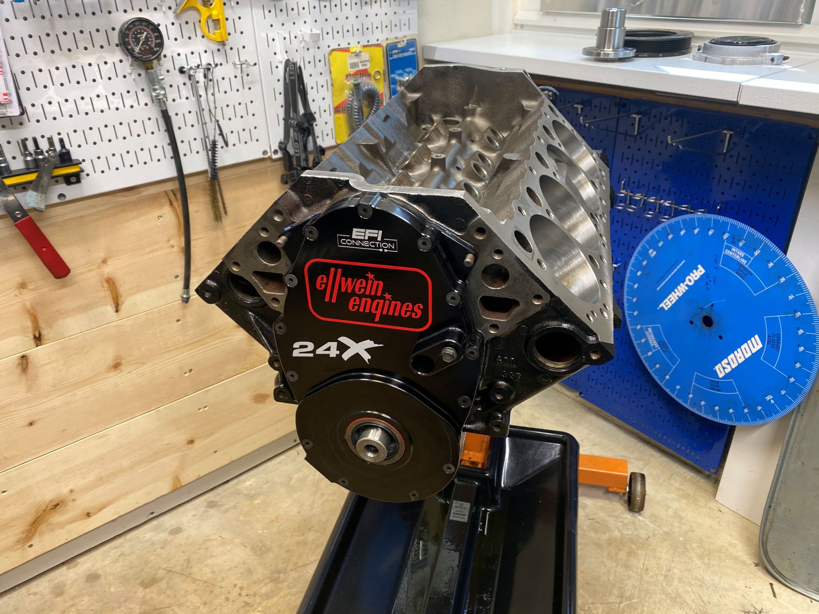
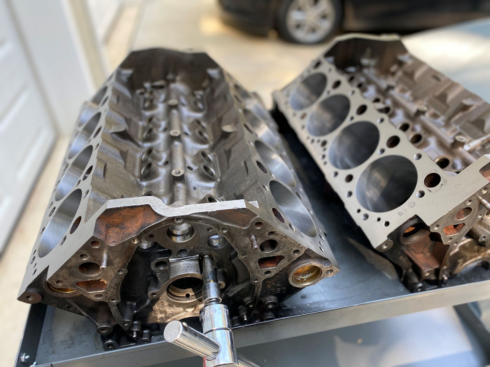
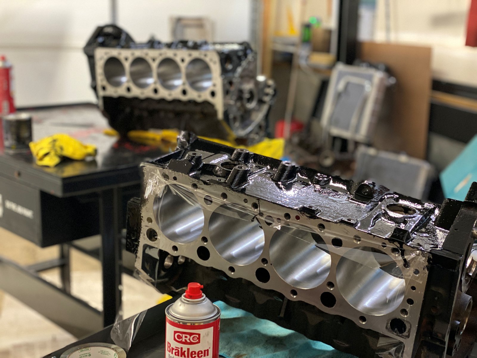
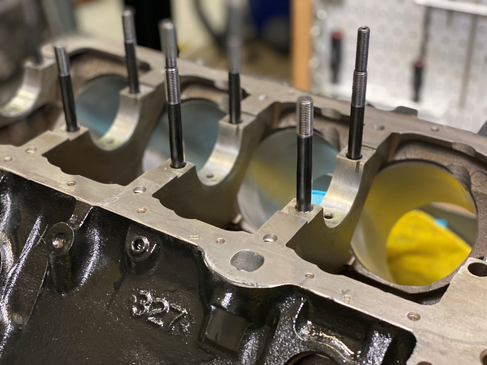
Doing block prep on 2 blocks today. EFI Connection block
is to the right with NO freeze plugs. They are each getting
the front oil galleries tapped for threaded plugs.
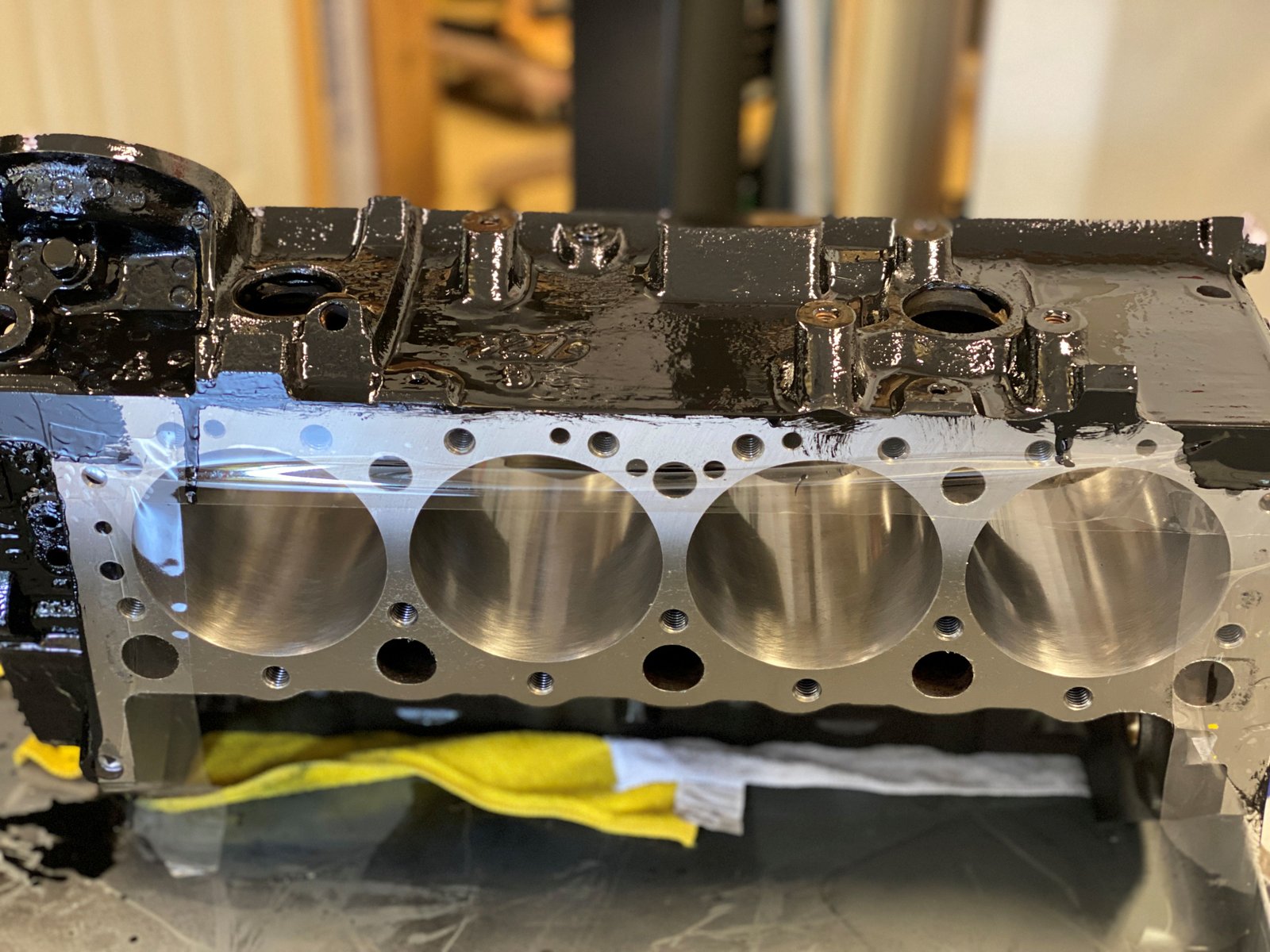
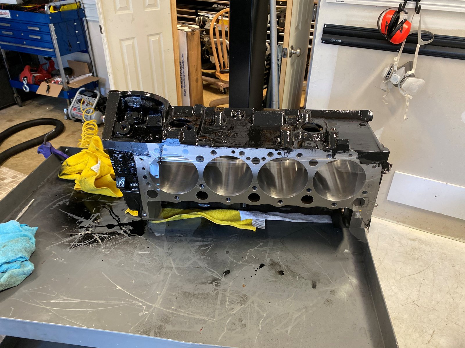
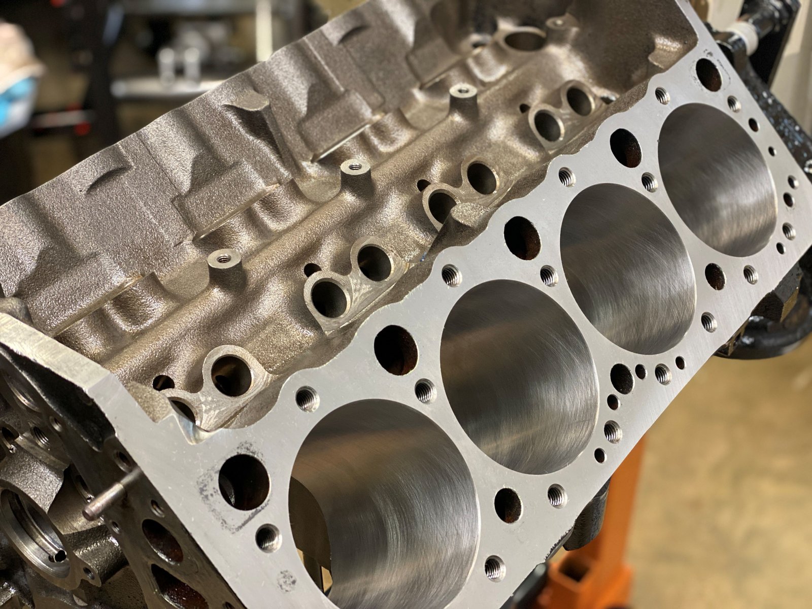
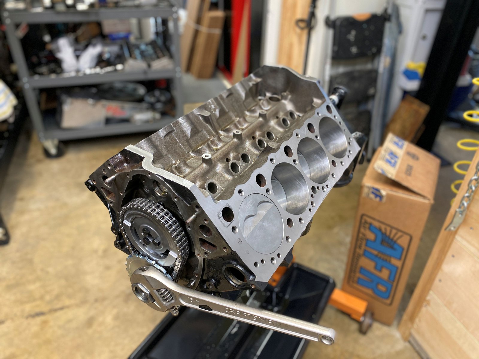
POR-15 black. EFI Connection block in the background.
Notice that the deck surface is only slightly decked. I only
take away what is required to make it square. Intake manifolds
fit better when blocks are minimum decked.
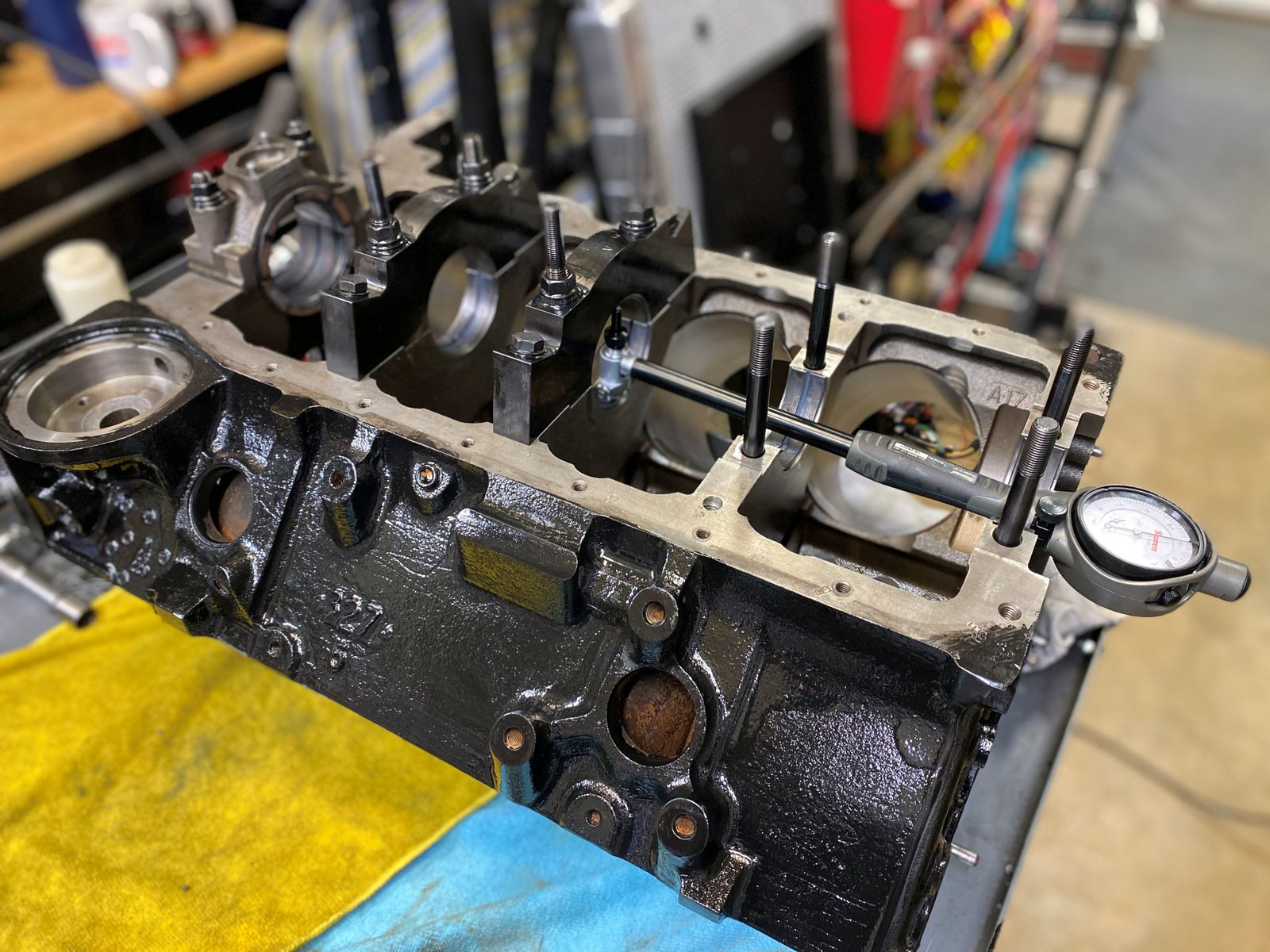
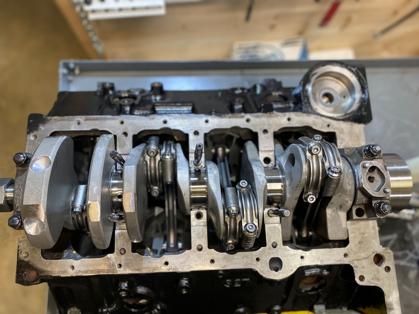
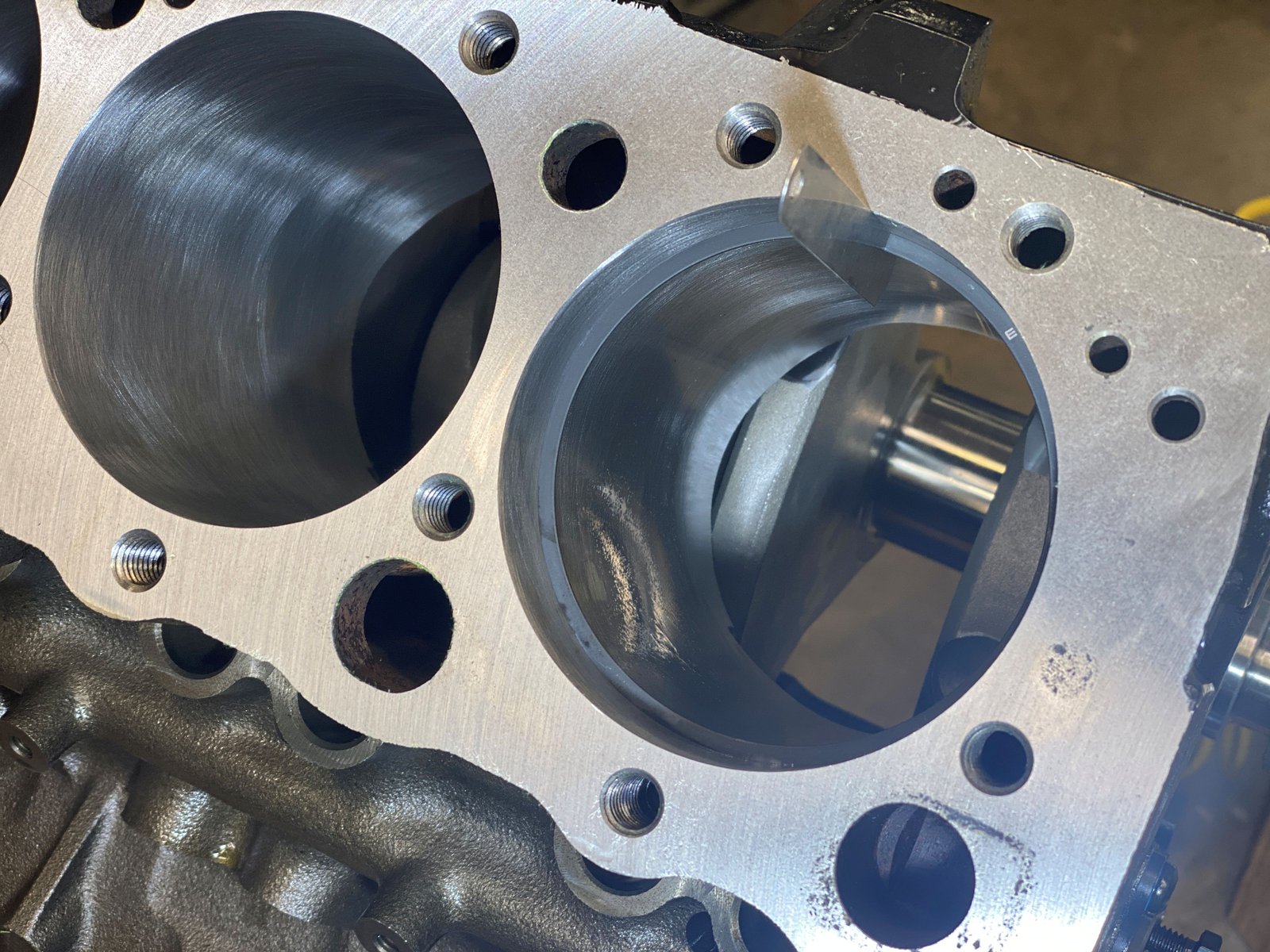
Today is the day to work on rotating assembly mock-up. I'll
measure bearing clearance and install the full rotating assembly and
mark where more block clearance is needed (if any).
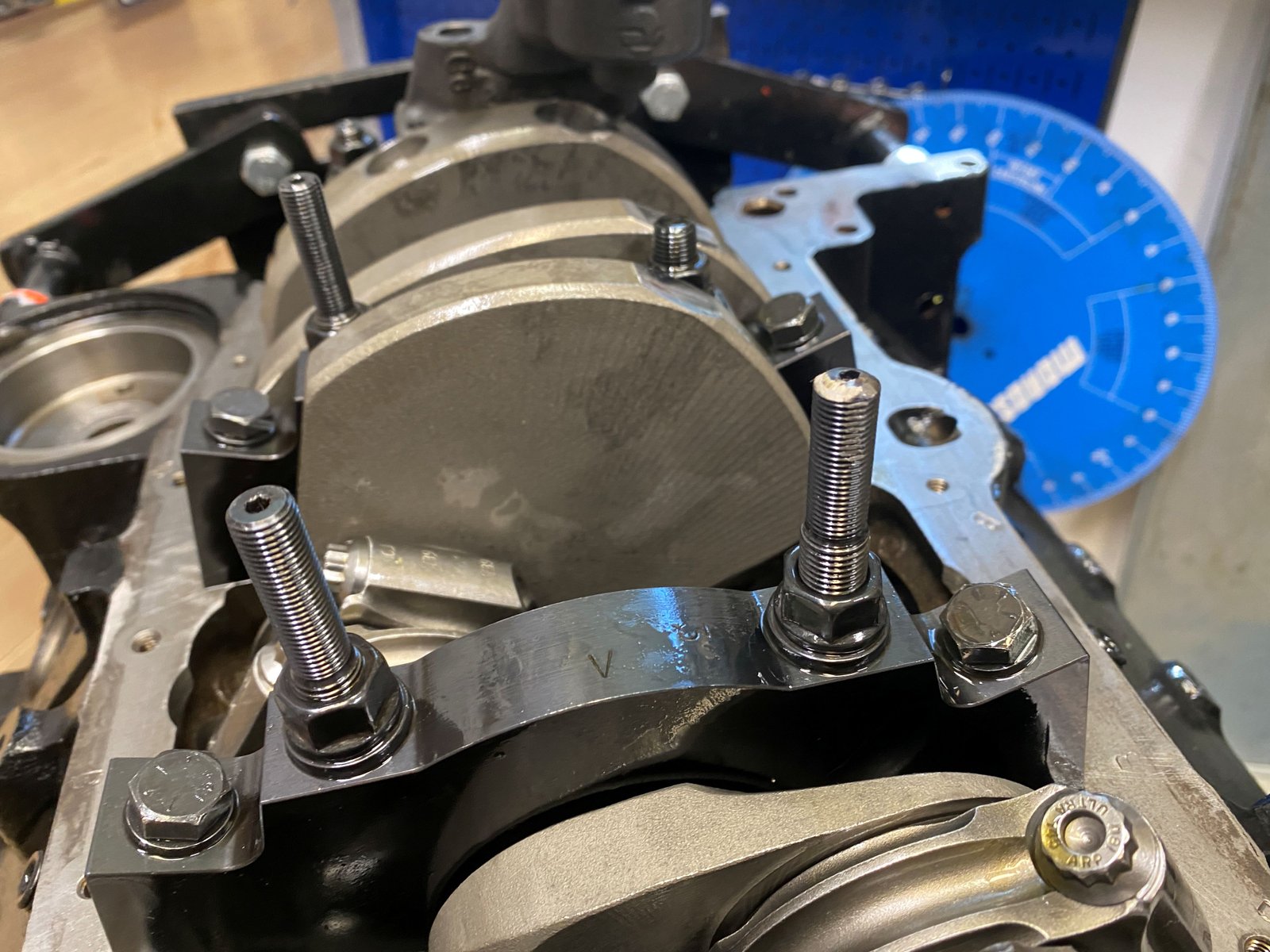
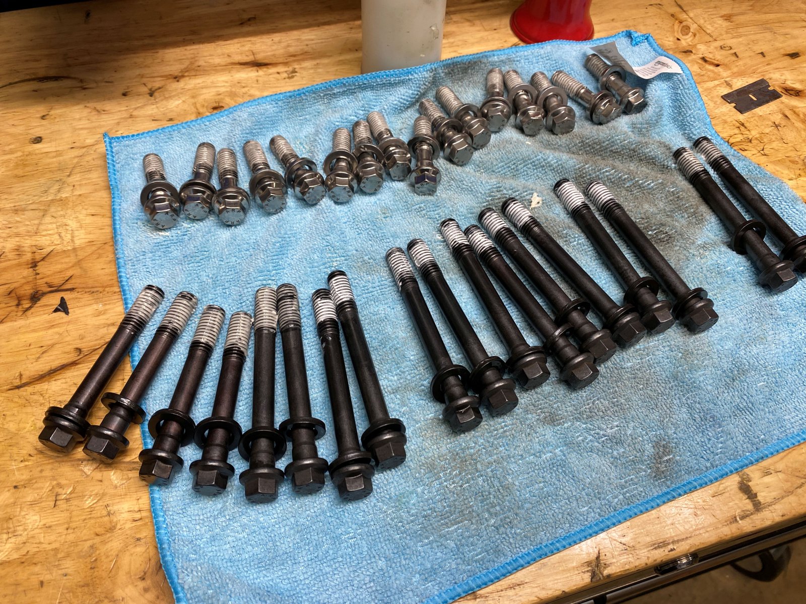
3 different sized main studs due to different sized main caps and
3 longer windage tray studs.
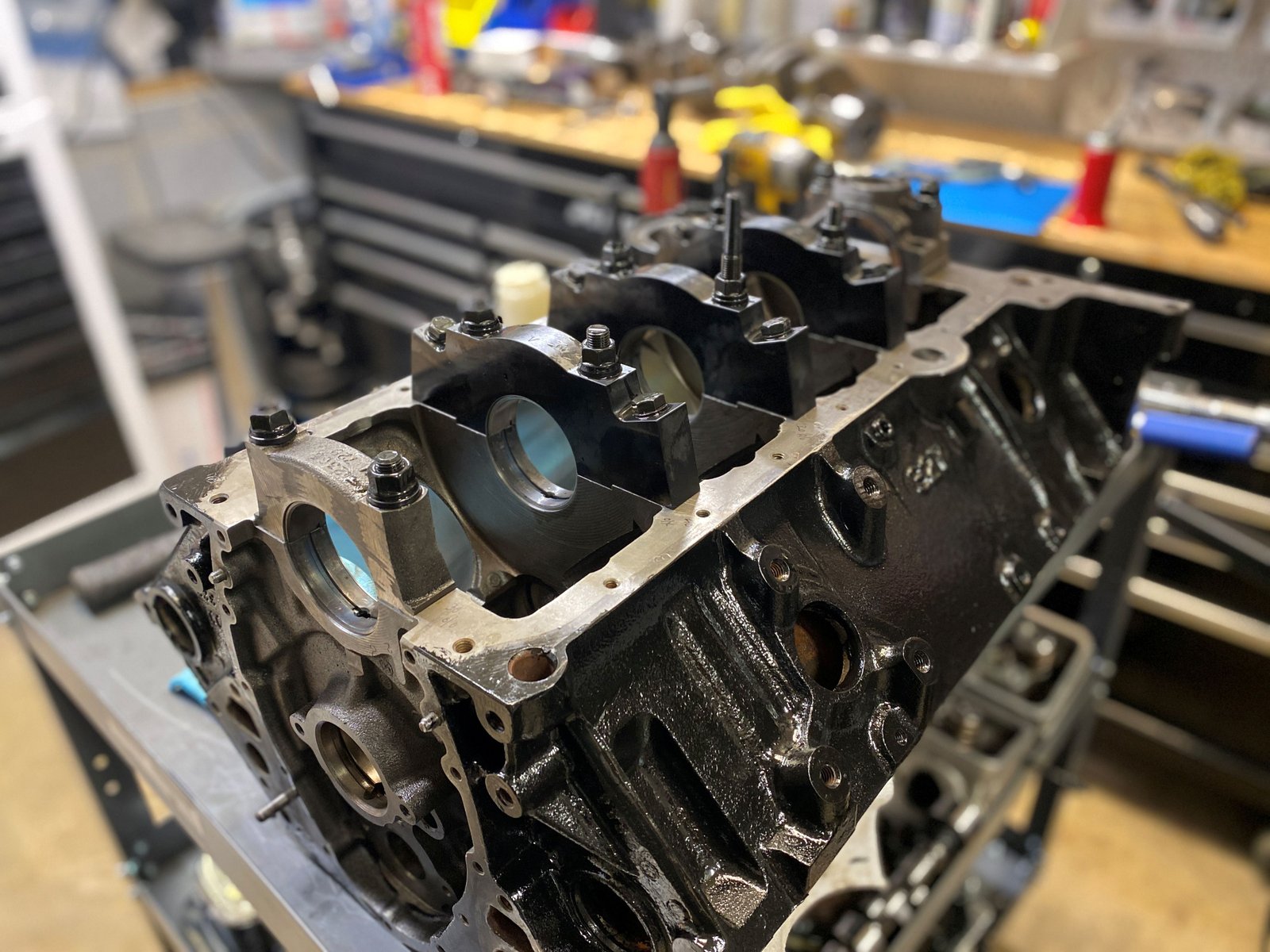
Mix of bearing sizes give the clearance that I'm happy with.
The main bearing clearance is .0025/.0027/.0027/.0028/.0037"
from #1 to #5. Using King M557XP bearings from standard to
.001" under to .001" over. Mixing 1/2 shells to get
as close to .0025" as possible---except at the #5 thrust
bearing of which the target is .0035".
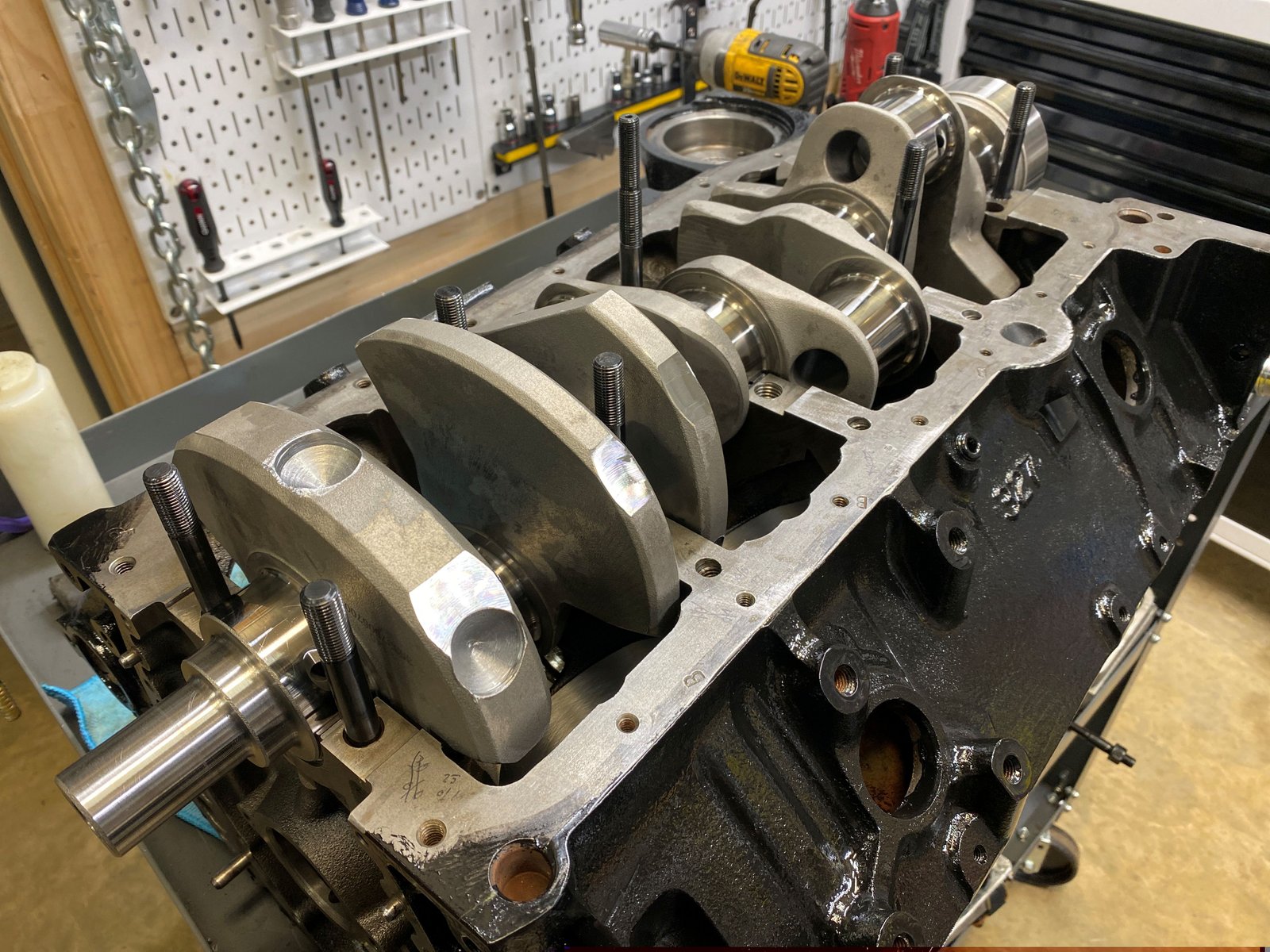
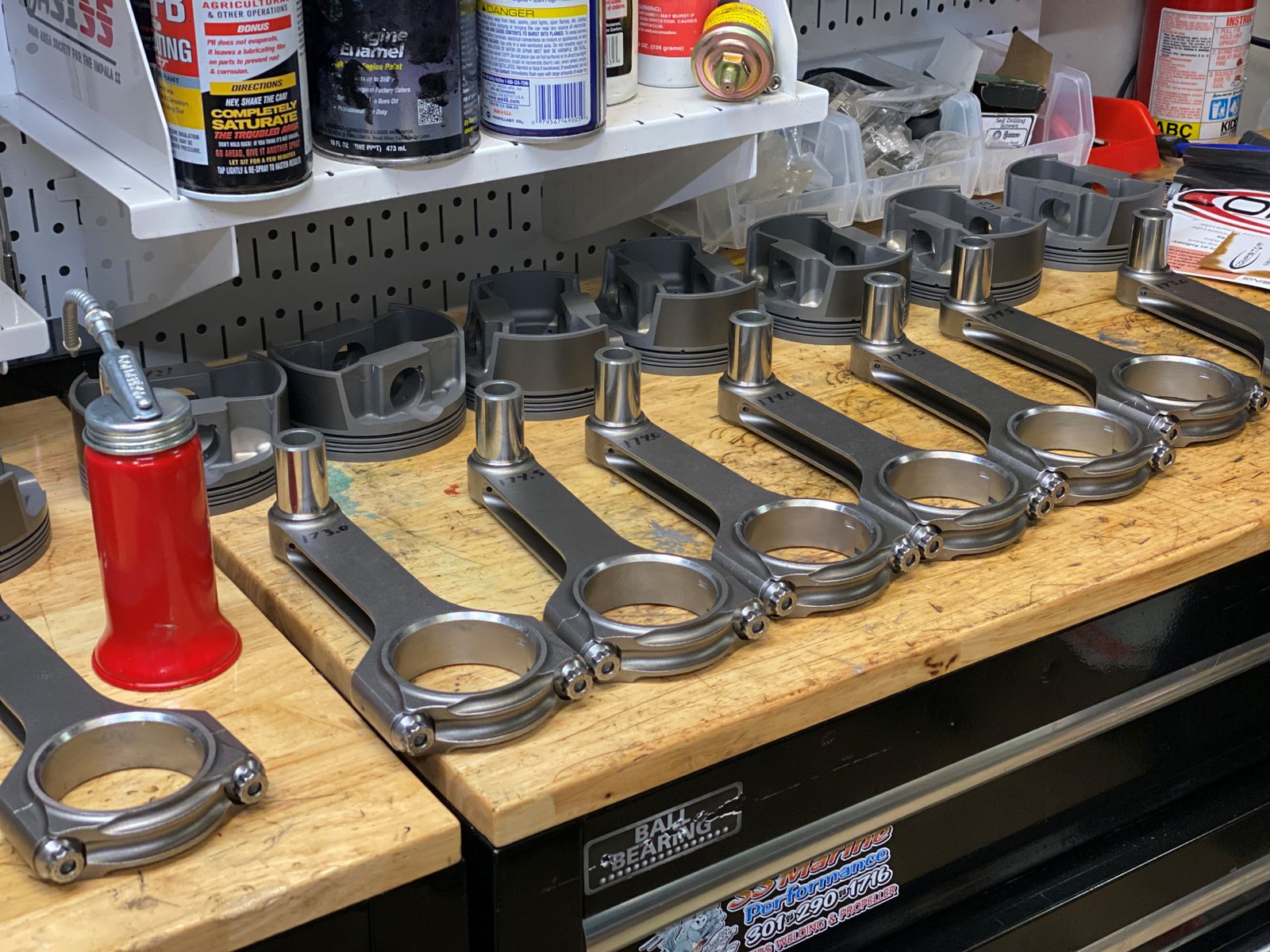
Now all are removed and the crankshaft will be set in place.
Eagle crankshaft balanced by Clinton Machine to 1725g neutral
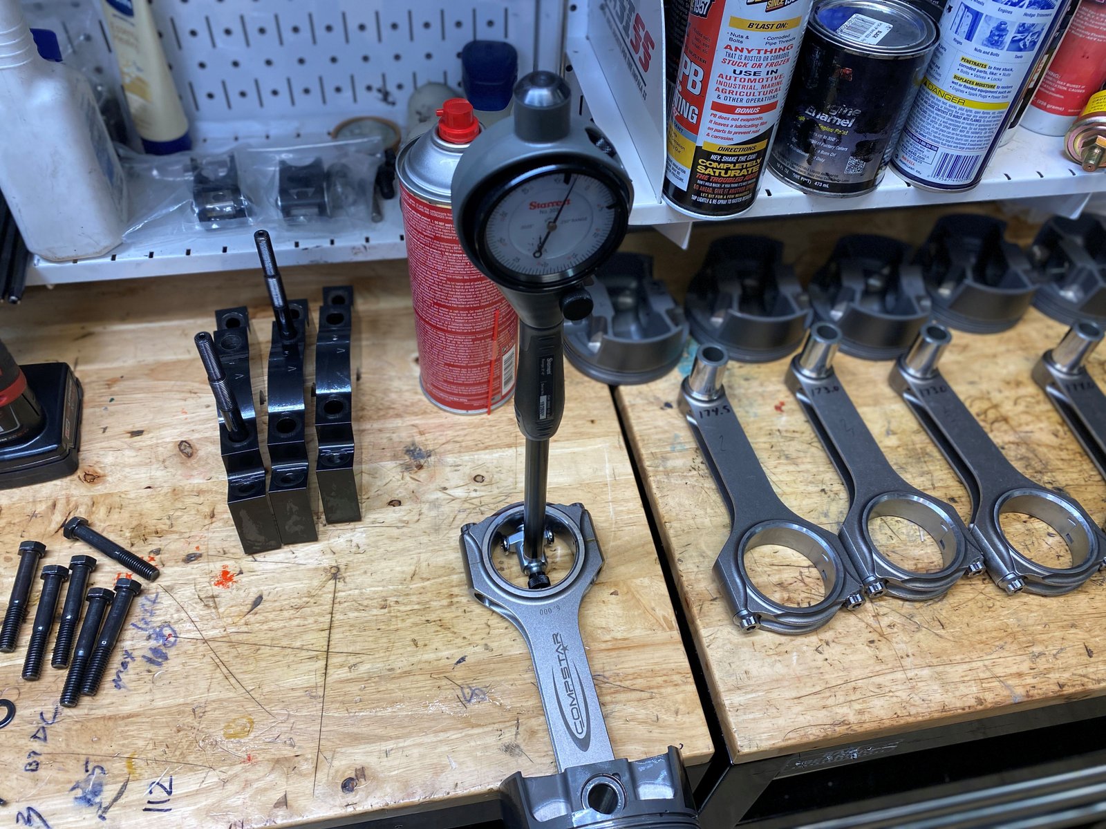
Compstar 6" rods and Mahle flat top pistons.
Piston to bore clearance verified to be .003"
King 807HPN bearings. All 8 rods measured from .0023 to
.0026" clearance.
Some rods are too close to the block (not shown in this
photo). I'll mark the area and grind after checking all
rod/piston combos.
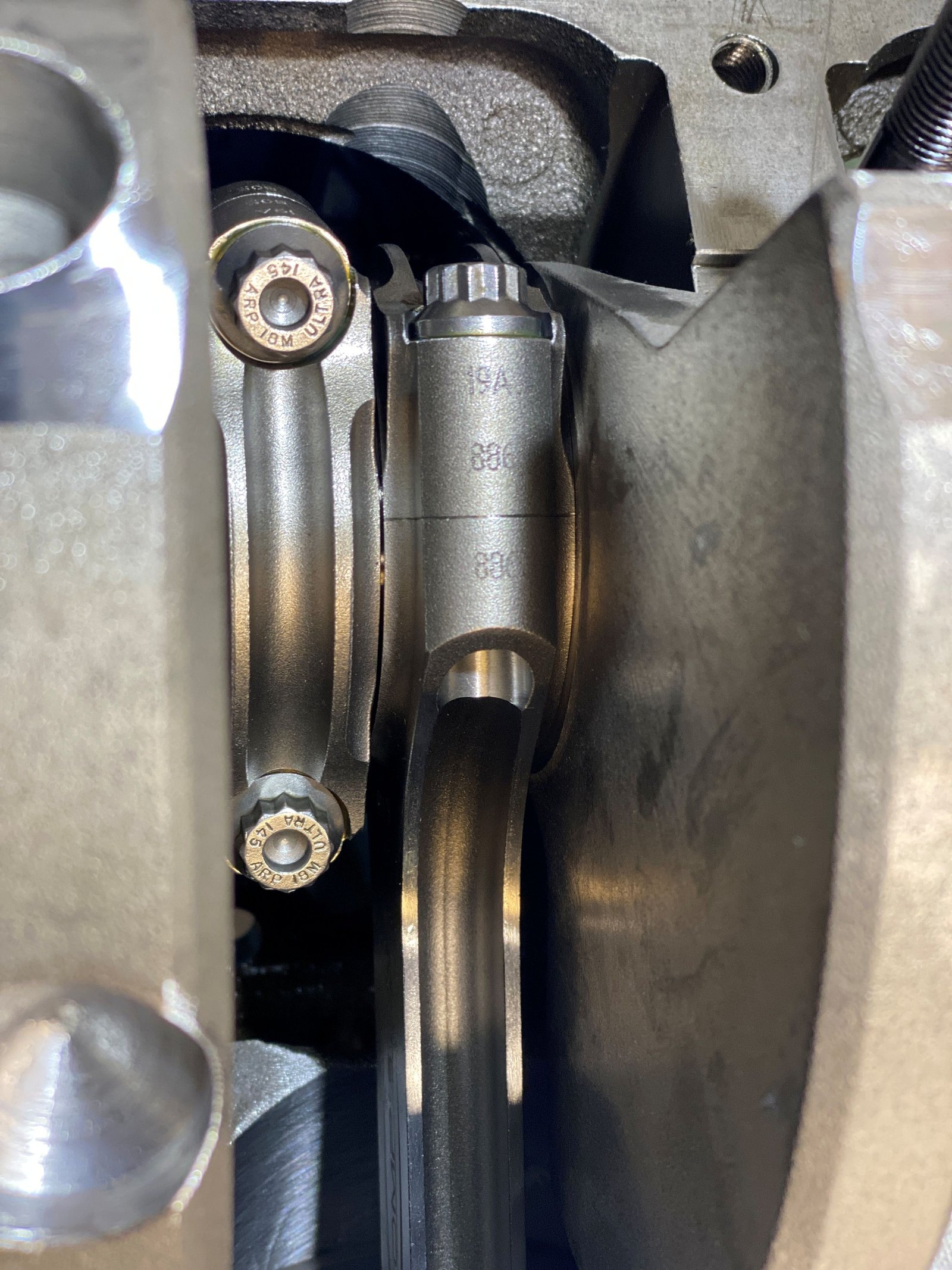
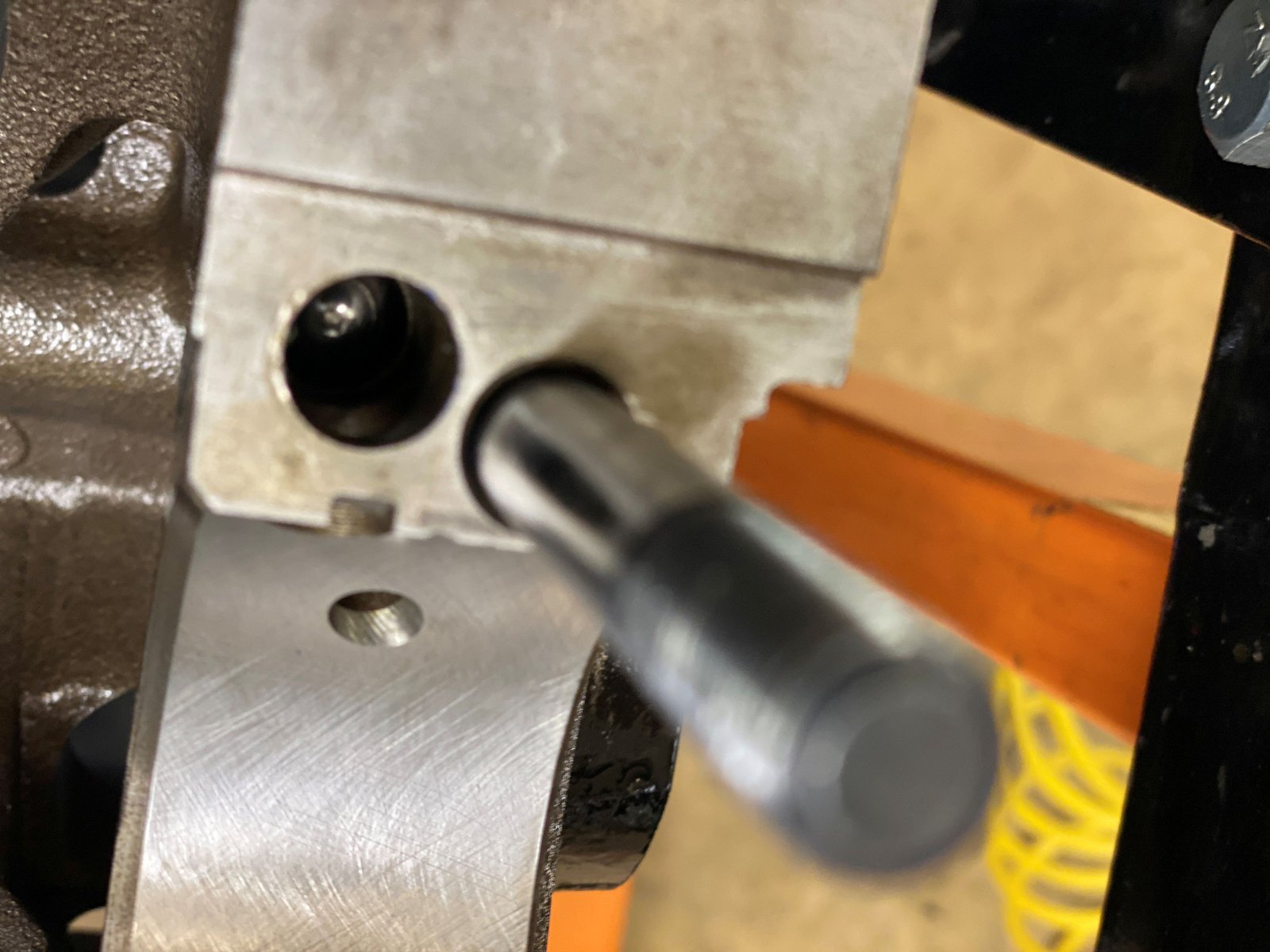
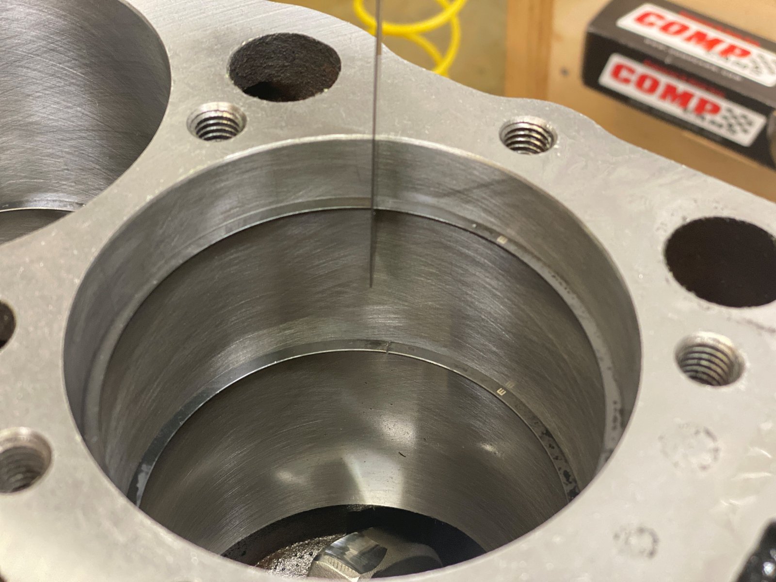
Here is a snap shot from my borescope which shows the cam tunnel
area and the rod having plenty of clearance. I can only see
this area using my borescope.
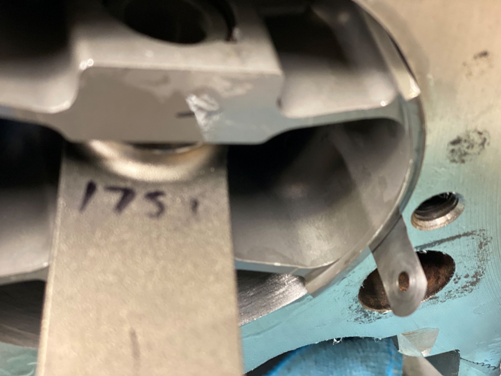
All assembled and mocked up. The areas marked in yellow are
the areas that require more clearance. Only about 4 spots
but the entire rotating assembly will come out and the block will
be clearanced and then cleaned.
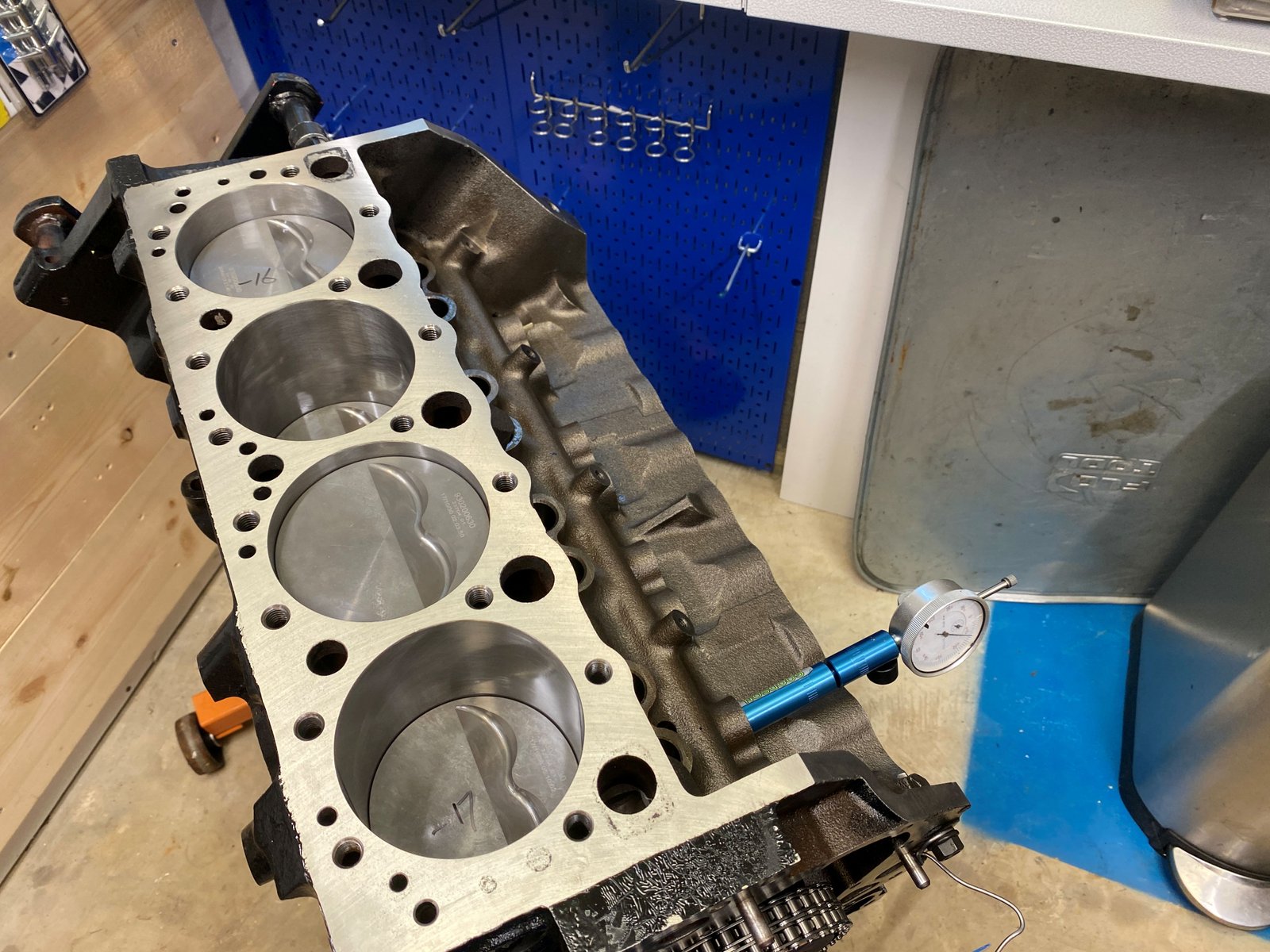
Also took the opportunity to measure piston to deck clearance,
(preliminary prior to full torque of caps and rods). #1 is at
.014" IN the hole. Also notice the paint is smudged at
the top-front. I did not notice until seeing this photo.
This is the block after cleaning and additional rod clearance.
Photo of steel ball oil galley plug, (for my records).
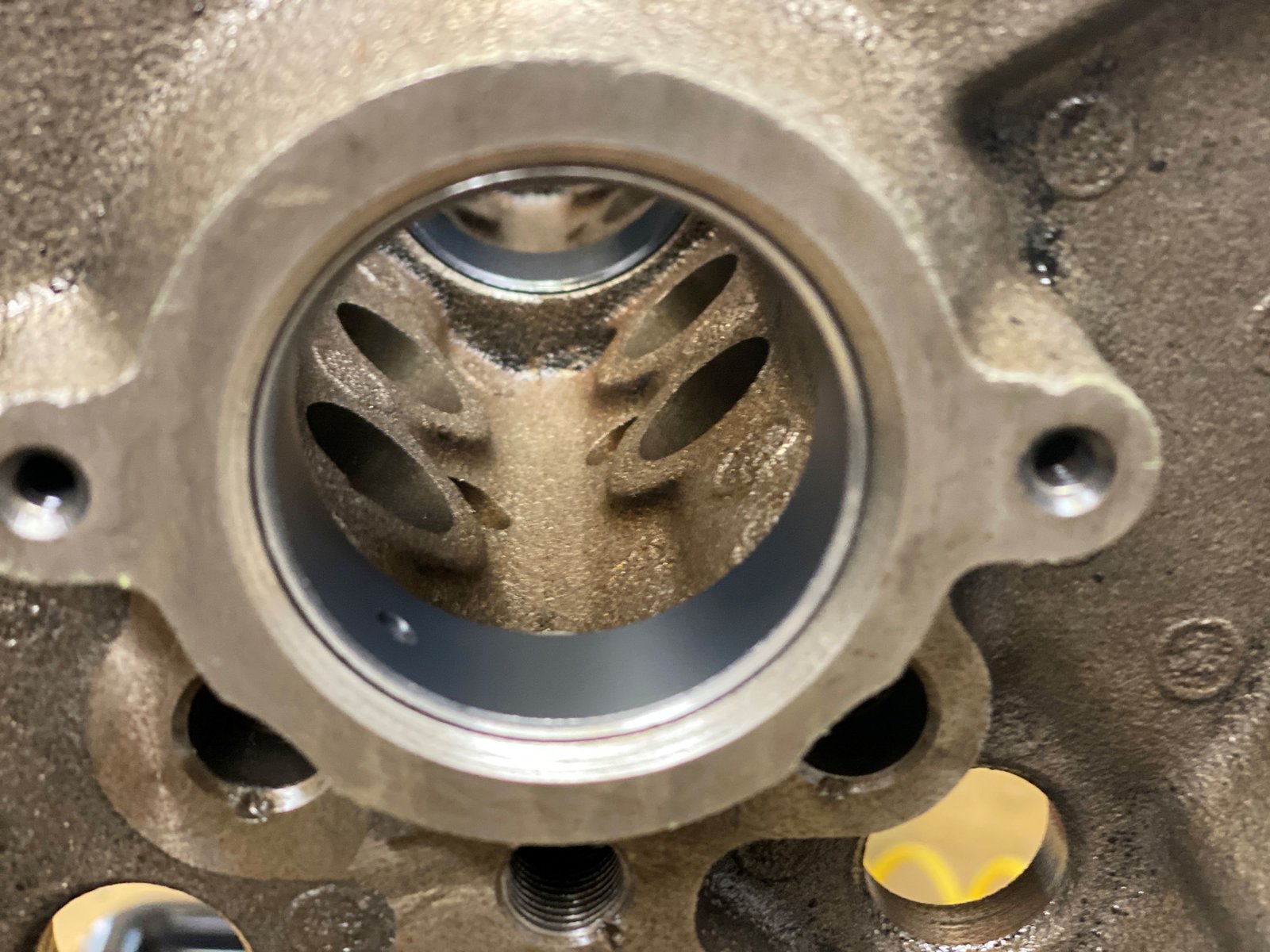
I had a set of coated cam bearings so why not install them for
Mike's motor. :)
Crankshaft installed and rear main thrust verified at
.006". This is before and after the rear main cap is
torqued to 80ft-lb.
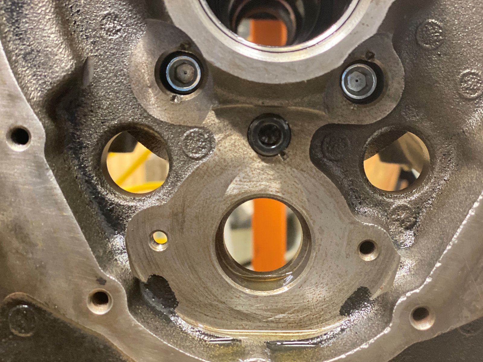
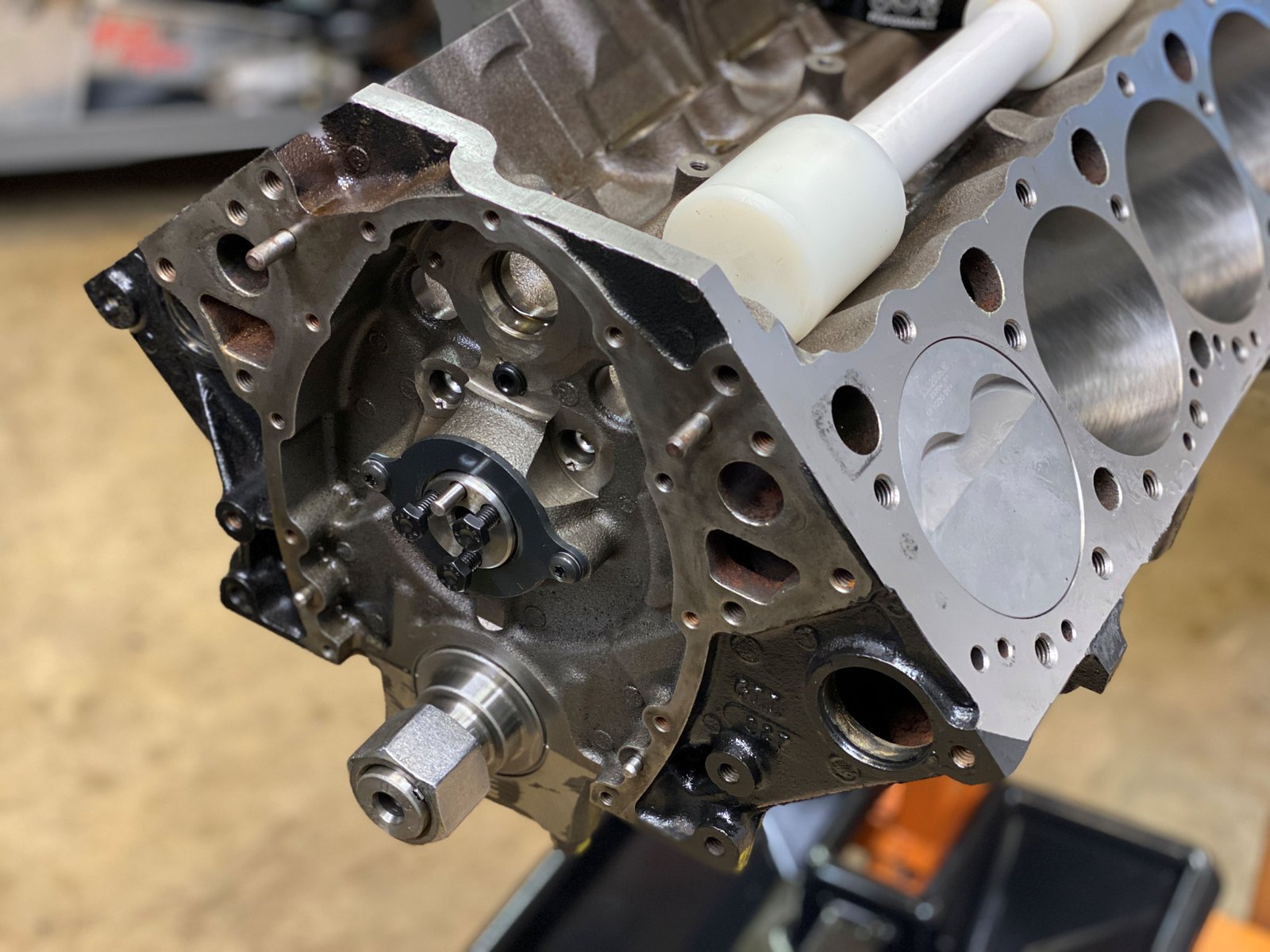
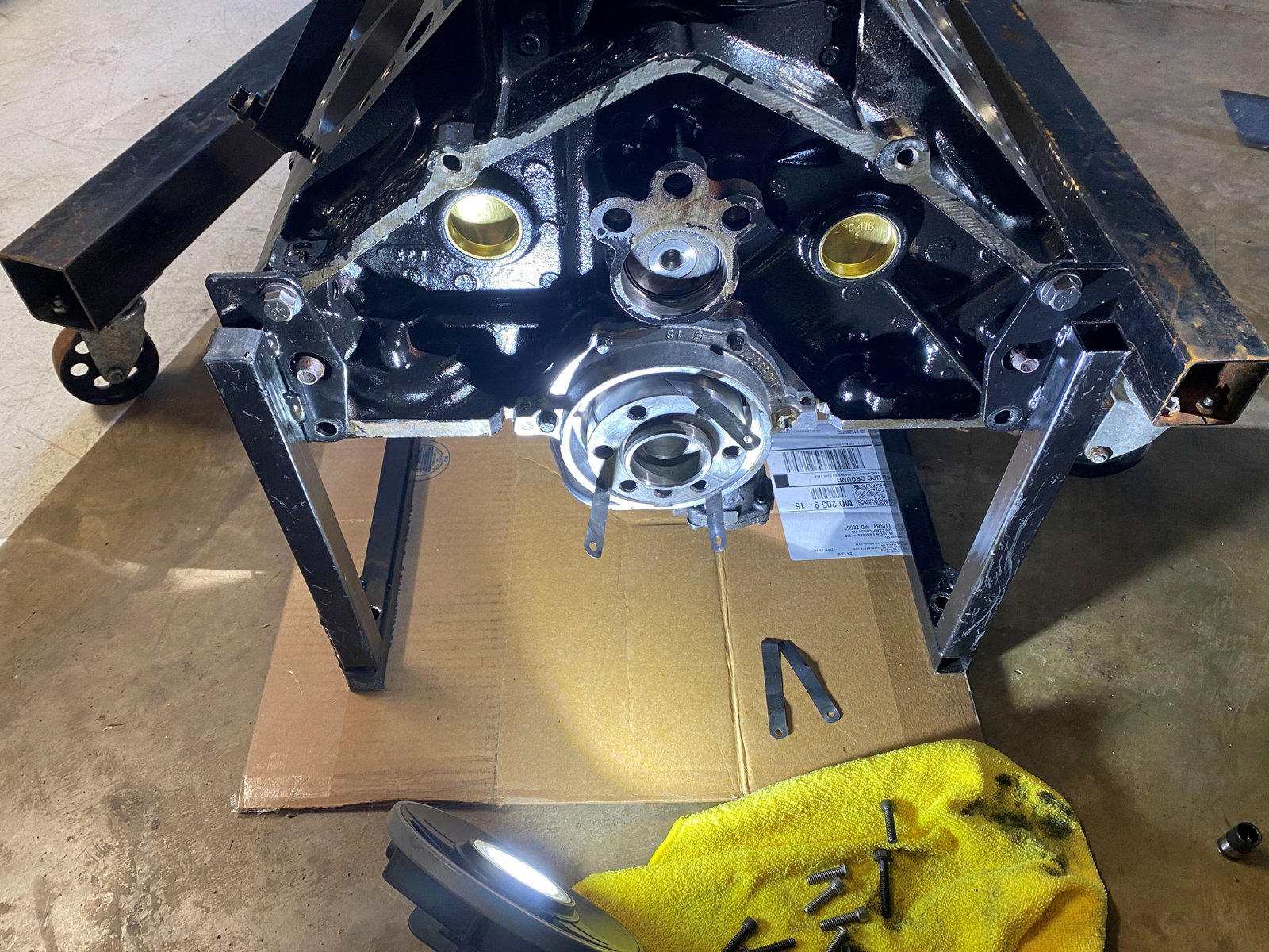
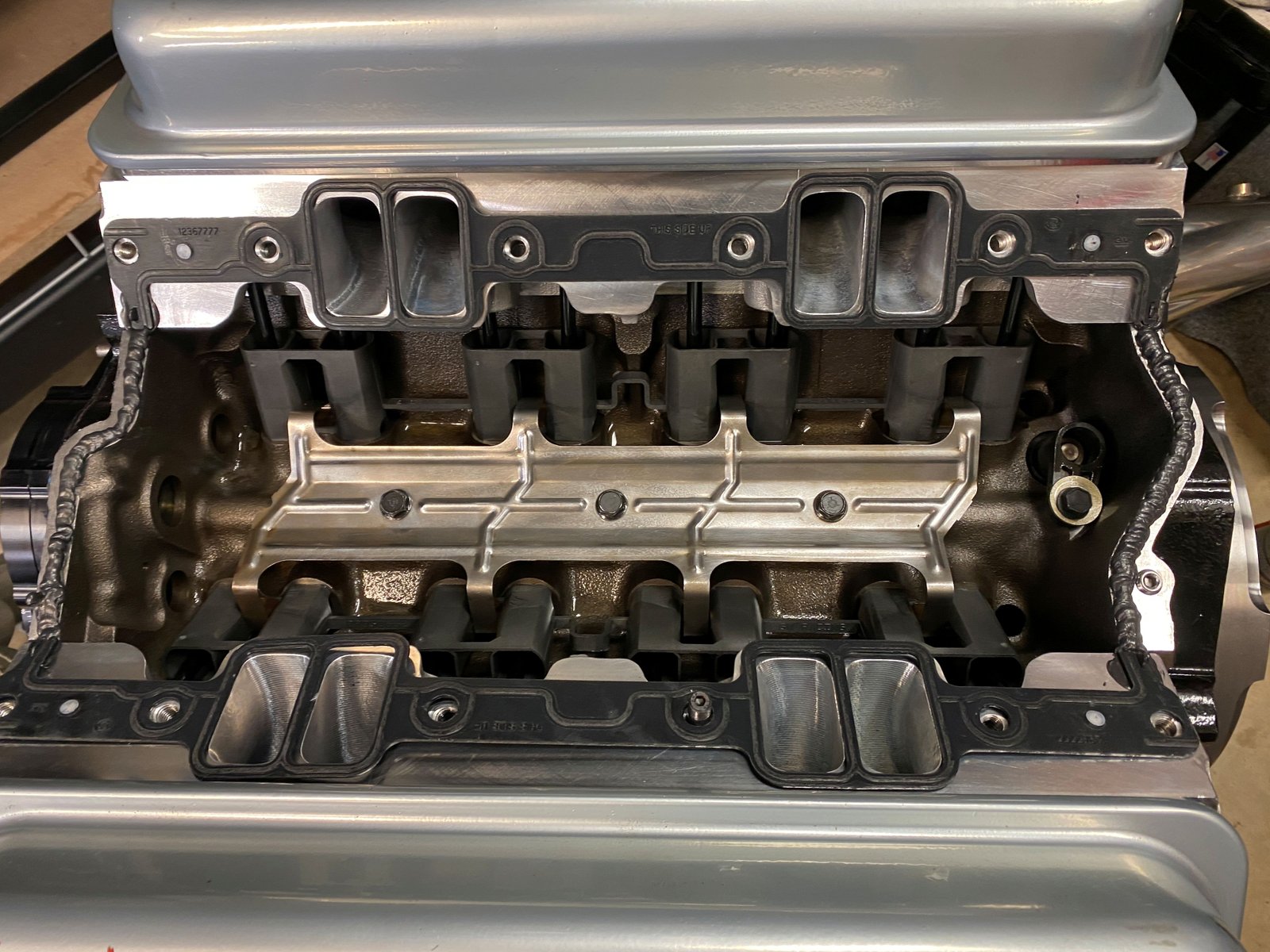
Here we have a photo of the front oil galley plugs.
These have been threaded by me in order to install the pipe
plugs. Notice the lifter valley plugs have oil weep holes.
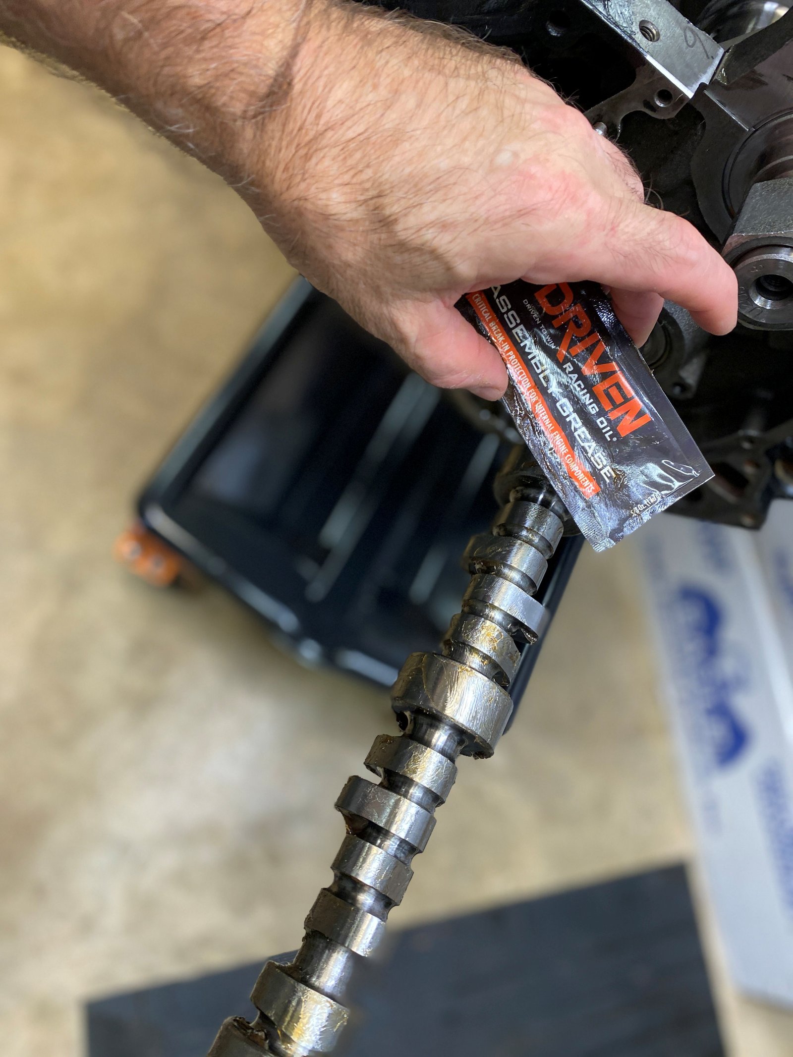
Billet core camshaft designed by Dennis Staff at Fast-Cat
porting service. This is on an Erson core.
.602/.584" lift...234/238 duration at .050"...112.5
LSA
Ring filing set up. The rings are 1mm thick. Mahle
pioneered the "thin" ring pack. I'm going to gap
the rings for street performance. 0.020" top ring and
0.018" second ring.
Top ring at .020"
2nd ring at .018"
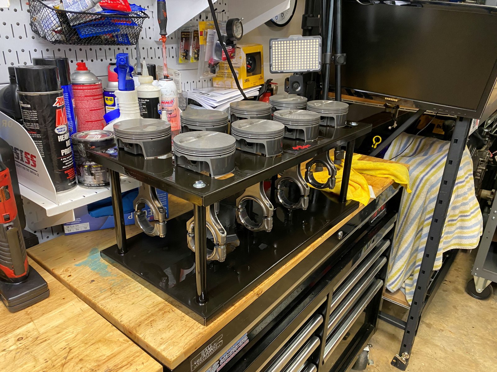
Washed the pistons/rods again in the SafetyKleen parts washer to
get them ready for ring installation.
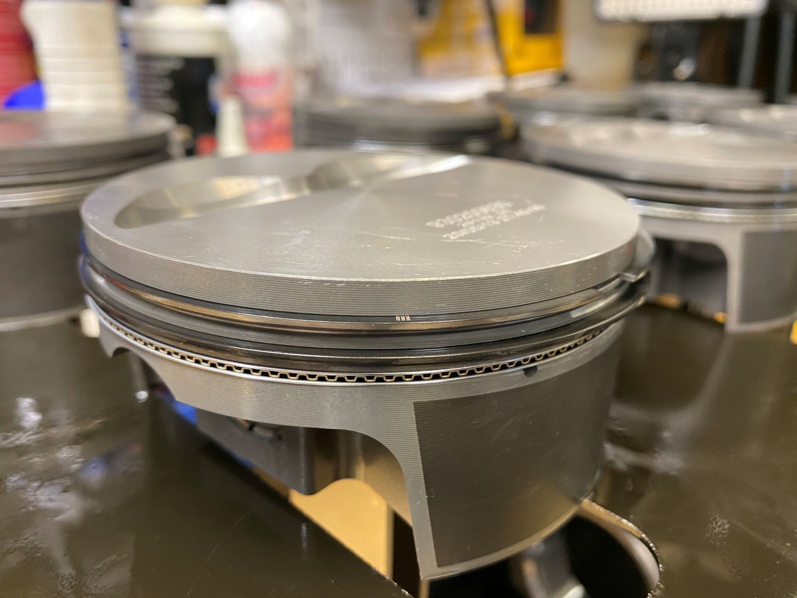
Oiled the rings with 30w oil and then wiped the excess
off. oiled the piston skirts. Be careful not to put too
much oil on the piston. Oil is good but not too much for
initial start-up. This is a nice close up of the premium
piston rings.
#1 and #2 rods/pistons in. Now it is time to install the
timing set. I need to verify that all rods can clear the
camshaft. The Compstar rods have good cam clearance but you
always have to check.
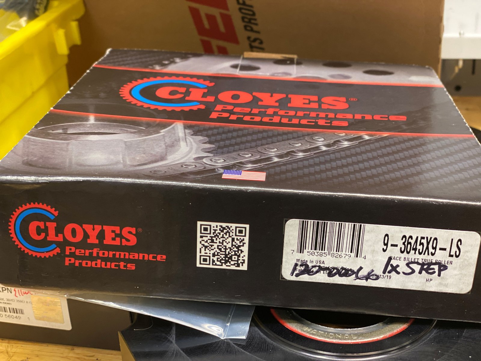
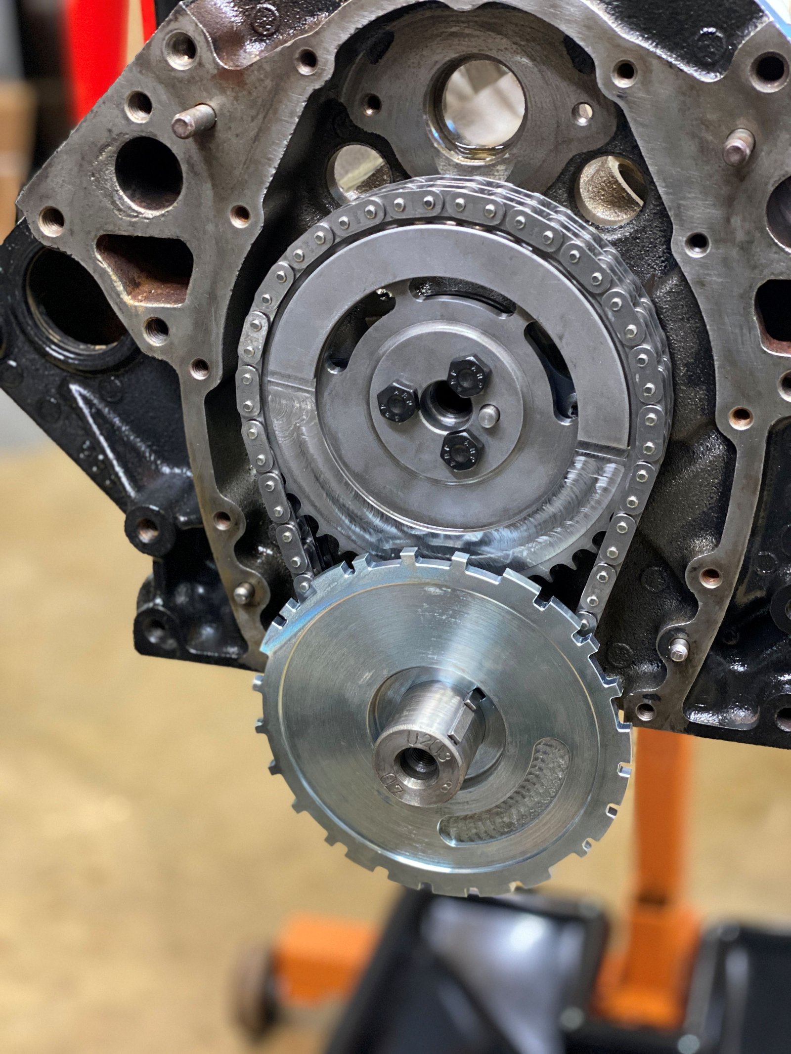
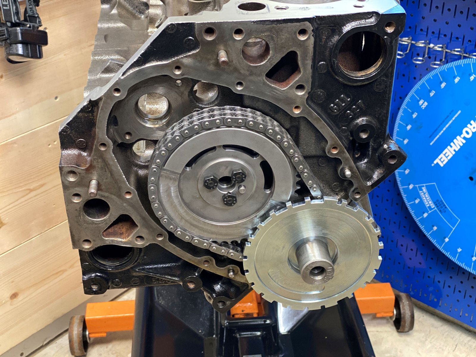
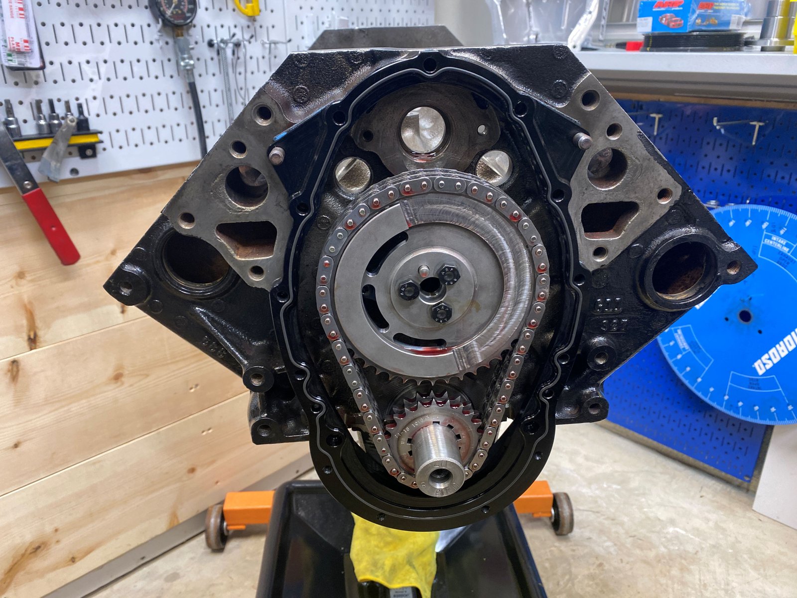
EFI Connection timing set for 24x crank and 1x cam
Cam not degreed yet. That is the next step after
installing all of the rods/pistons.
The timing set is nice in that it has advance or retard by 2
deg increments.
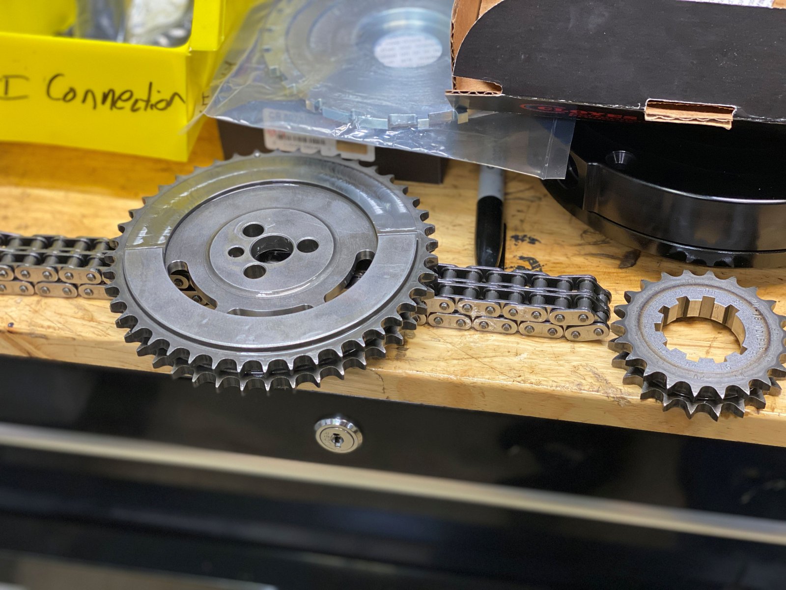
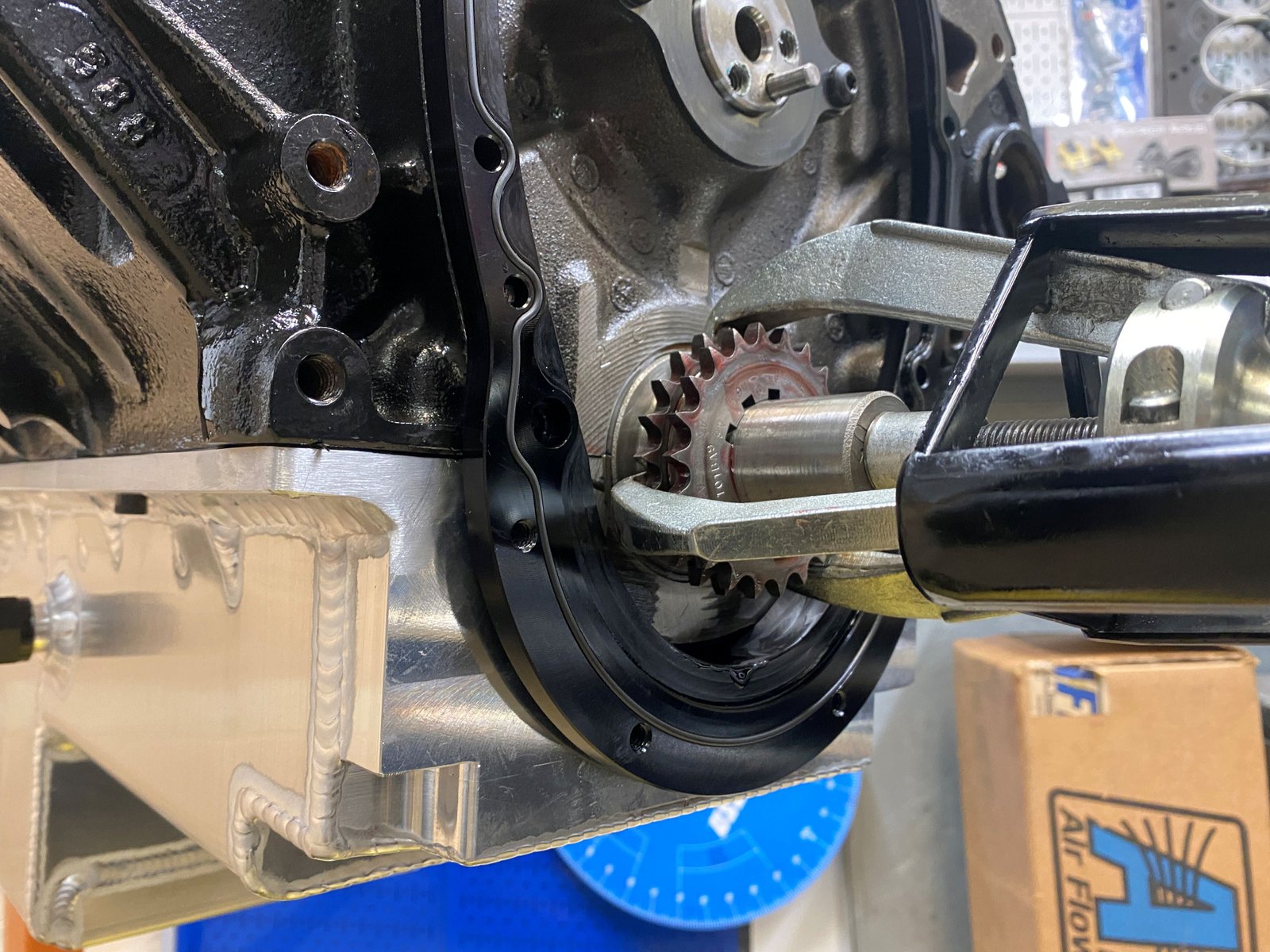
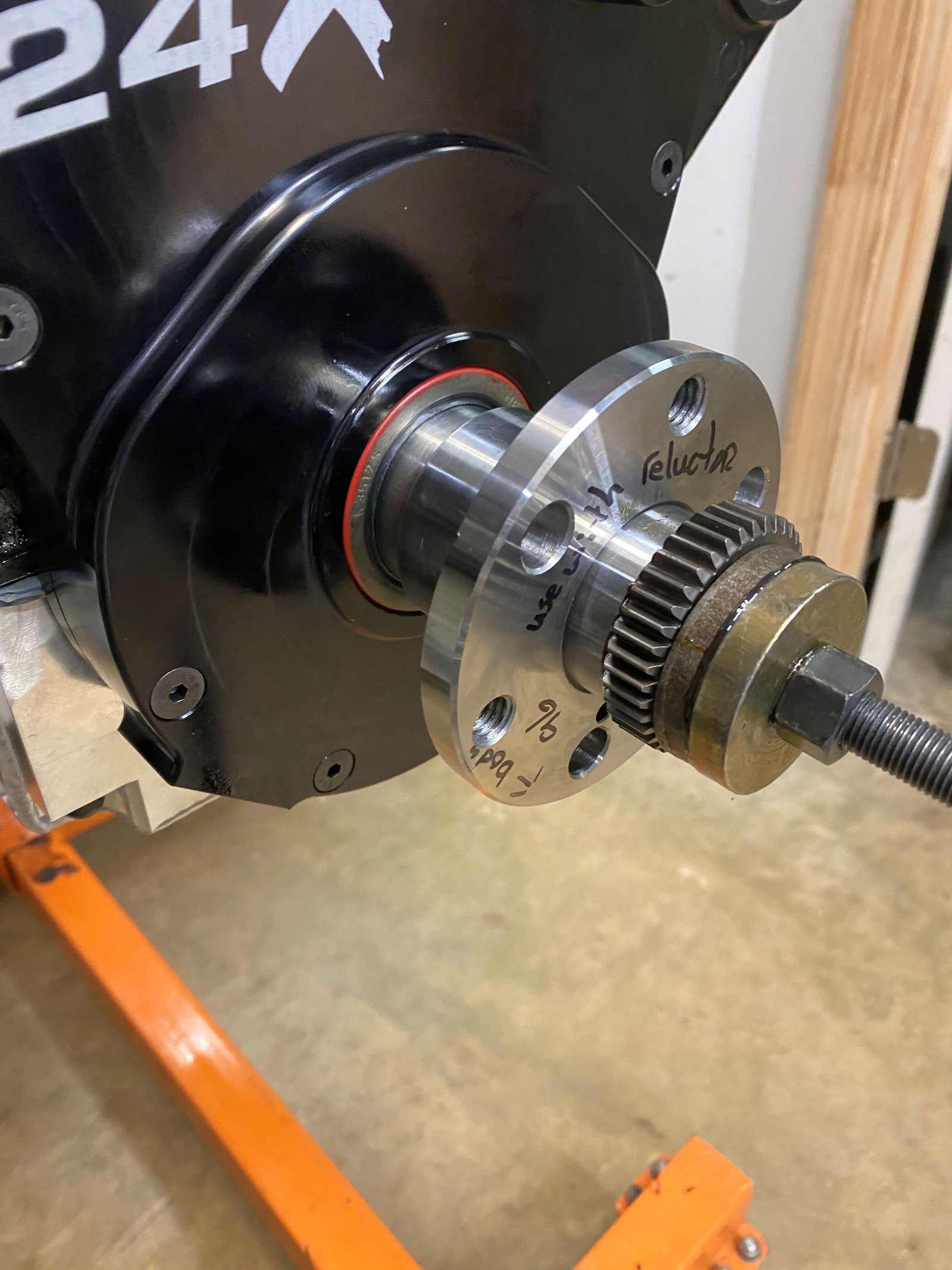
Would you look at the size of that reluctor! Much bigger
than the previous version. How can it fit under the timing
cover?
EFI Connection is planning to make available a 2-piece LT1
timing cover. This is a pre production unity.
All pistons/rods installed and no cam interference.
Still to-do: torque the rod bolts and degree check the cam.
Rod bolt torque and rod side clearance. Side clearance is
.022"
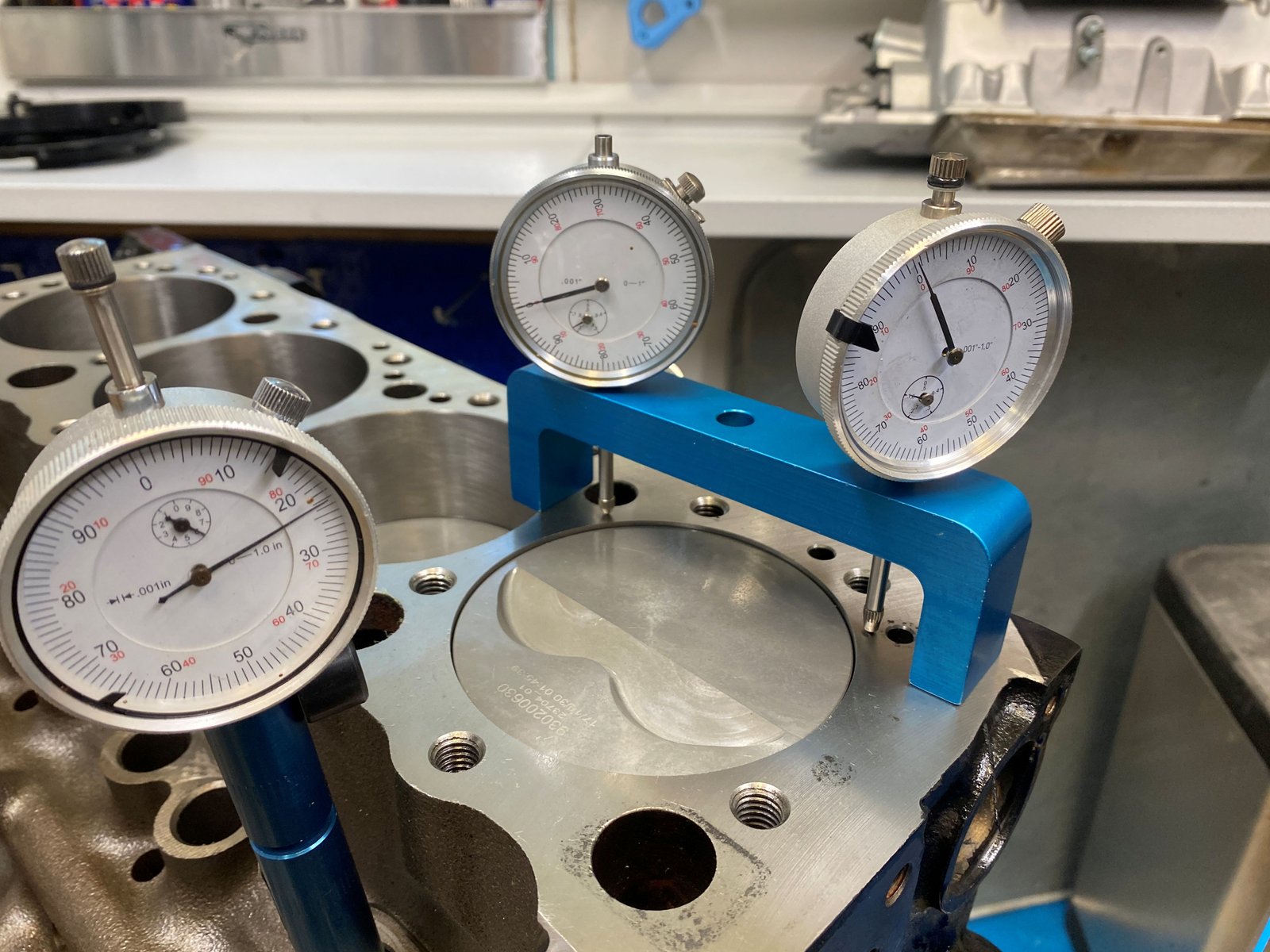
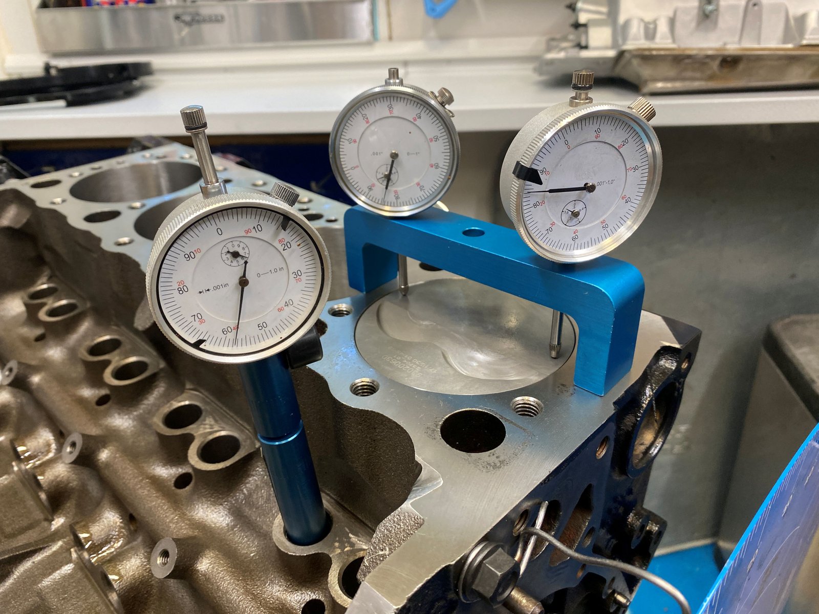
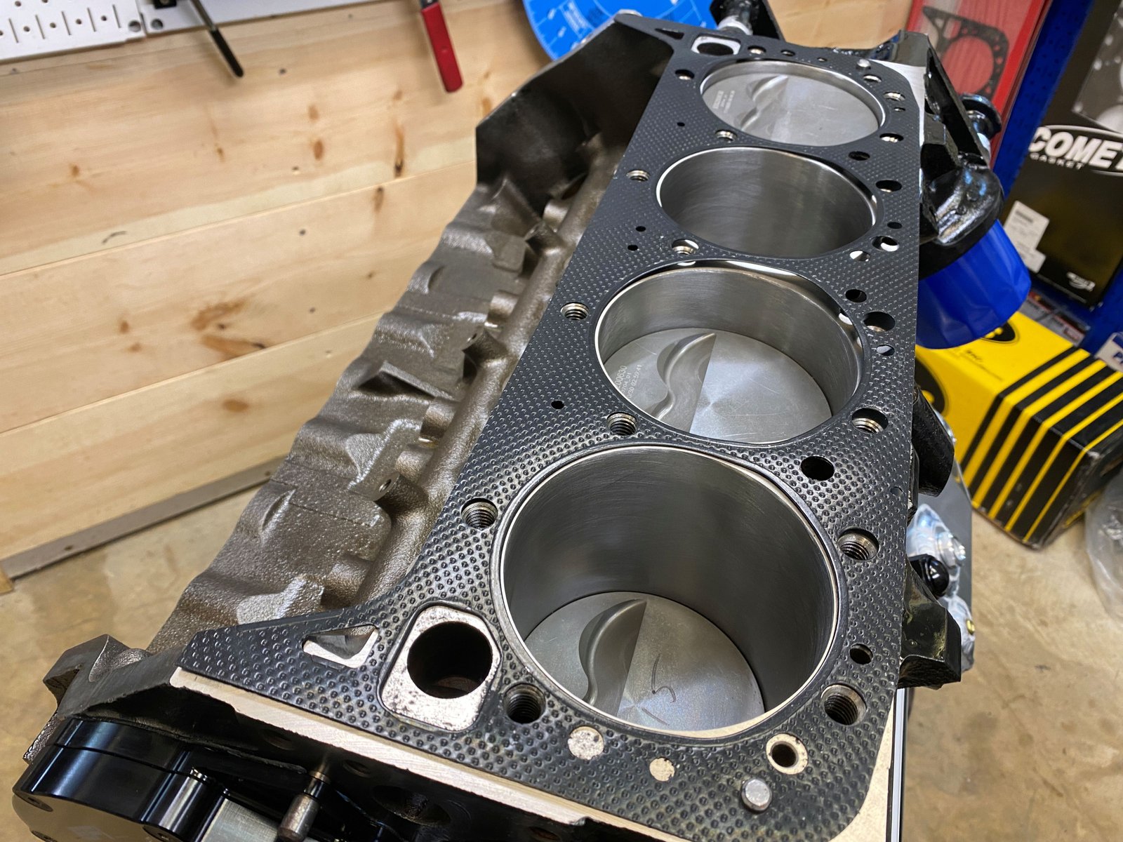
Now finding how far the pistons are in the hole. I measure
at the 4 corners to see how square the decking is. Here is where I
zero out the 2 gauges on the deck...
...then move them over to the piston. Here at #1 piston it is
-.015" (in the hole). Over at #7 it's -.014"
And #2 is -.017" and #8 is -.016" Not perfect but
it rarely is.
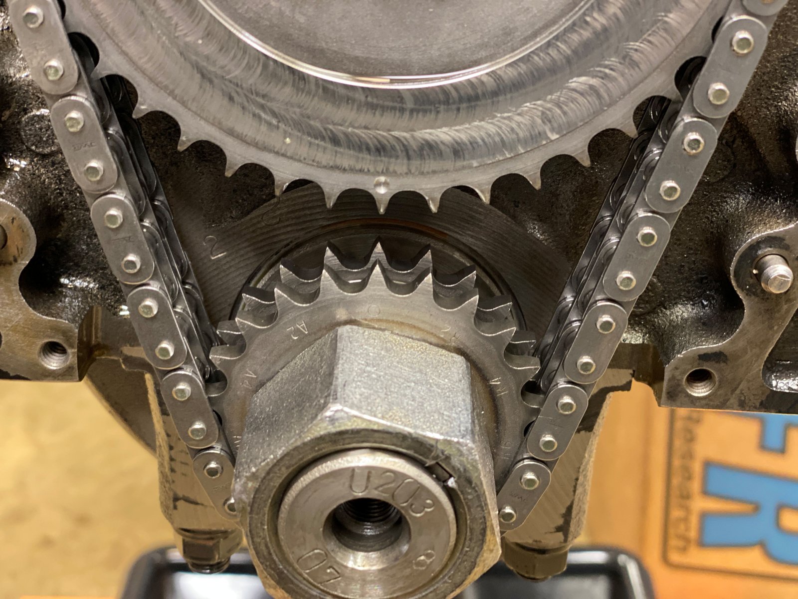
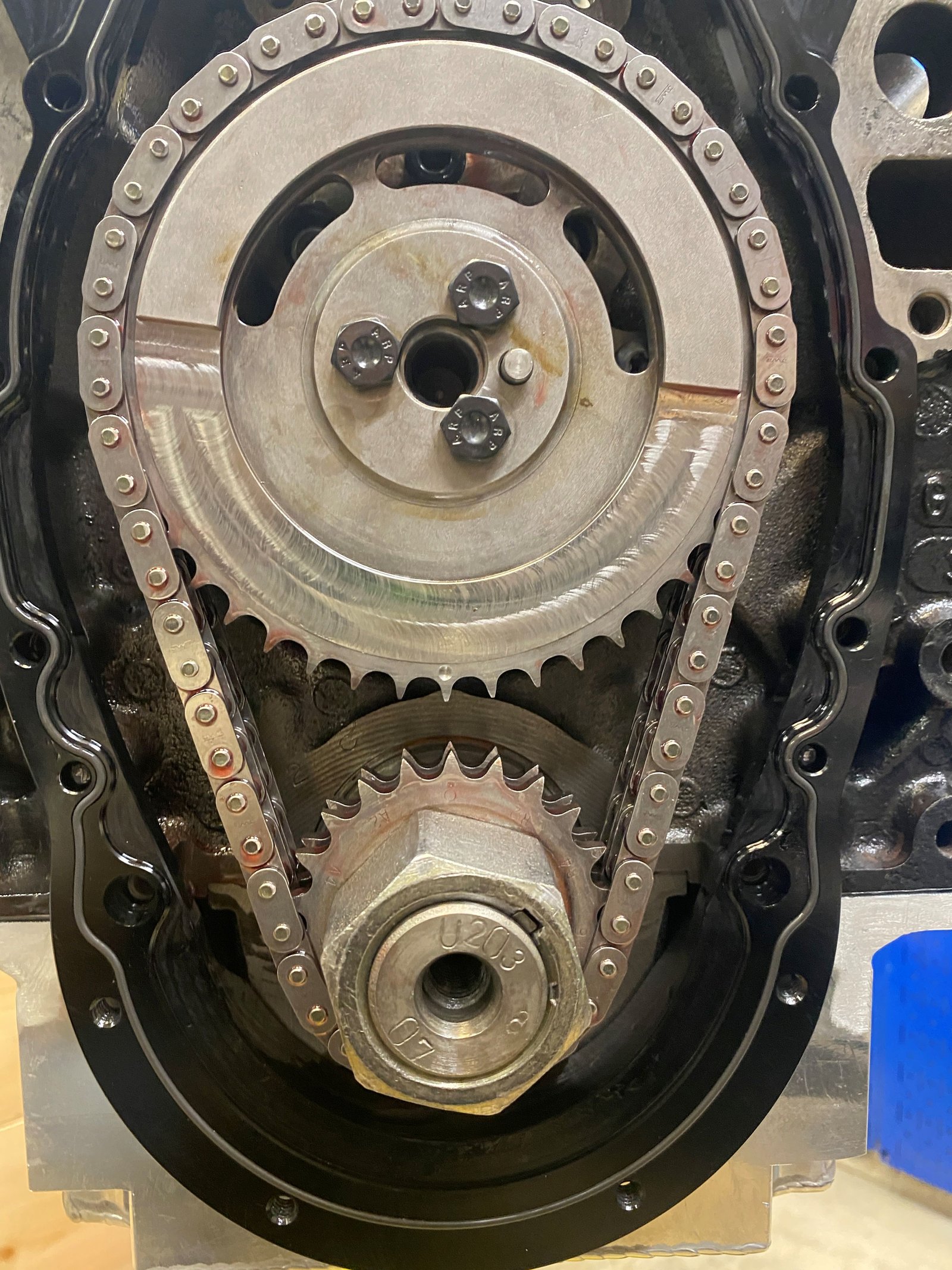
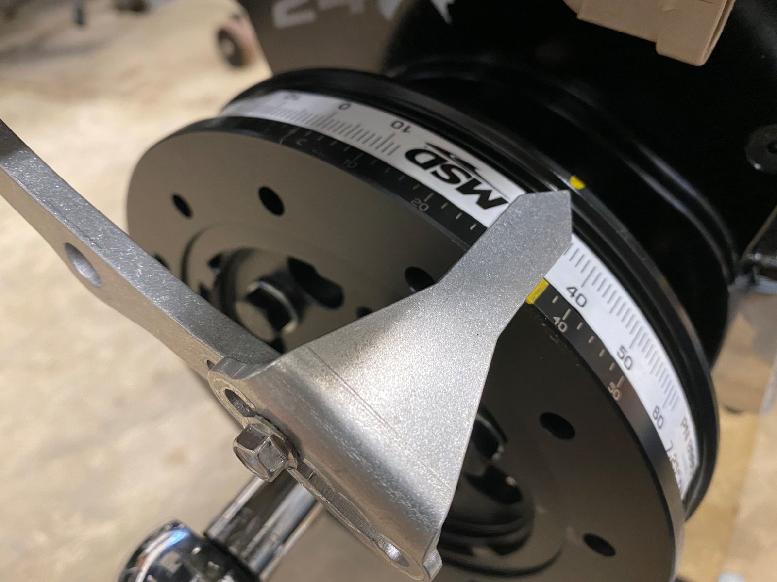
Zero on the crank sprocket gave me 108 deg ICL and the cam card
calls for 108-110 deg (it's 112+4). I moved the crank sprocket
to the -2 position and now I have 110.5deg ICL. I might move
it back to 108.
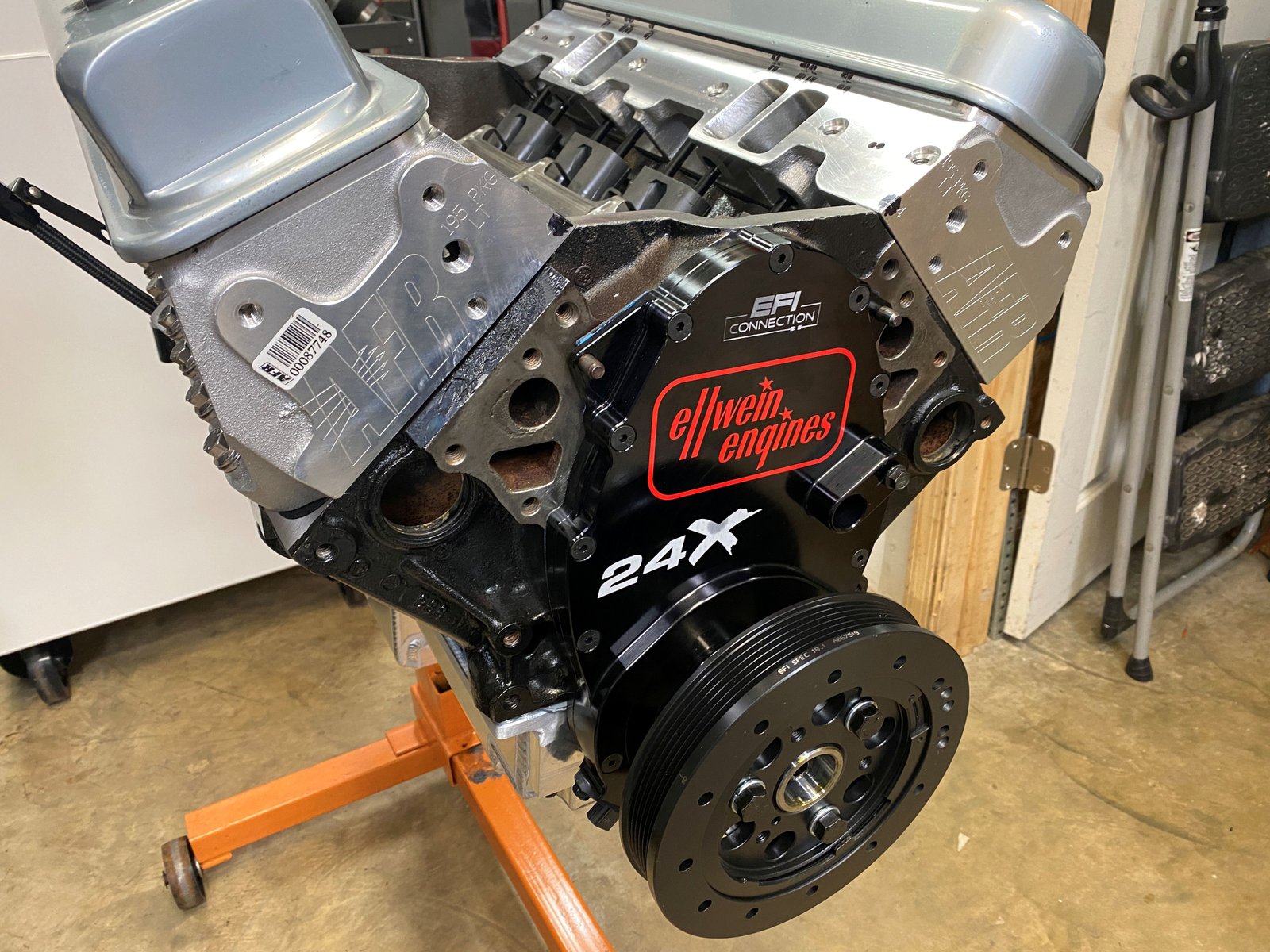
Now the EFI Connection 24x reluctor is installed on the crank nose.
And now the 2-piece timing cover.
And now my decal.
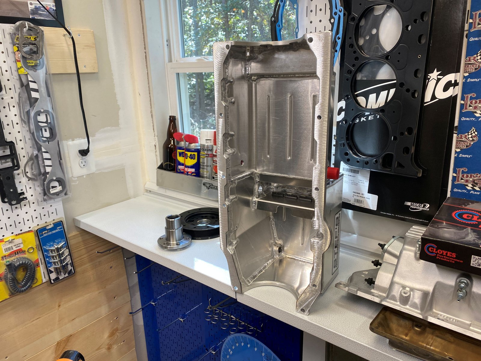
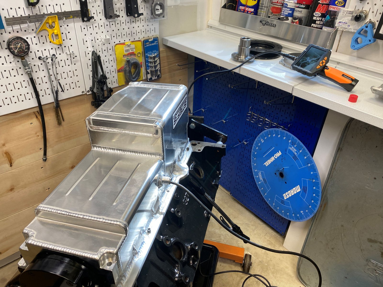
Ellwein/Stef's pan. Some modification needs to be performed.
Checking fit and for interference. One longer main stud hits.
I ground down the top of the stud, cleaned it and reinstalled /
torqued it.
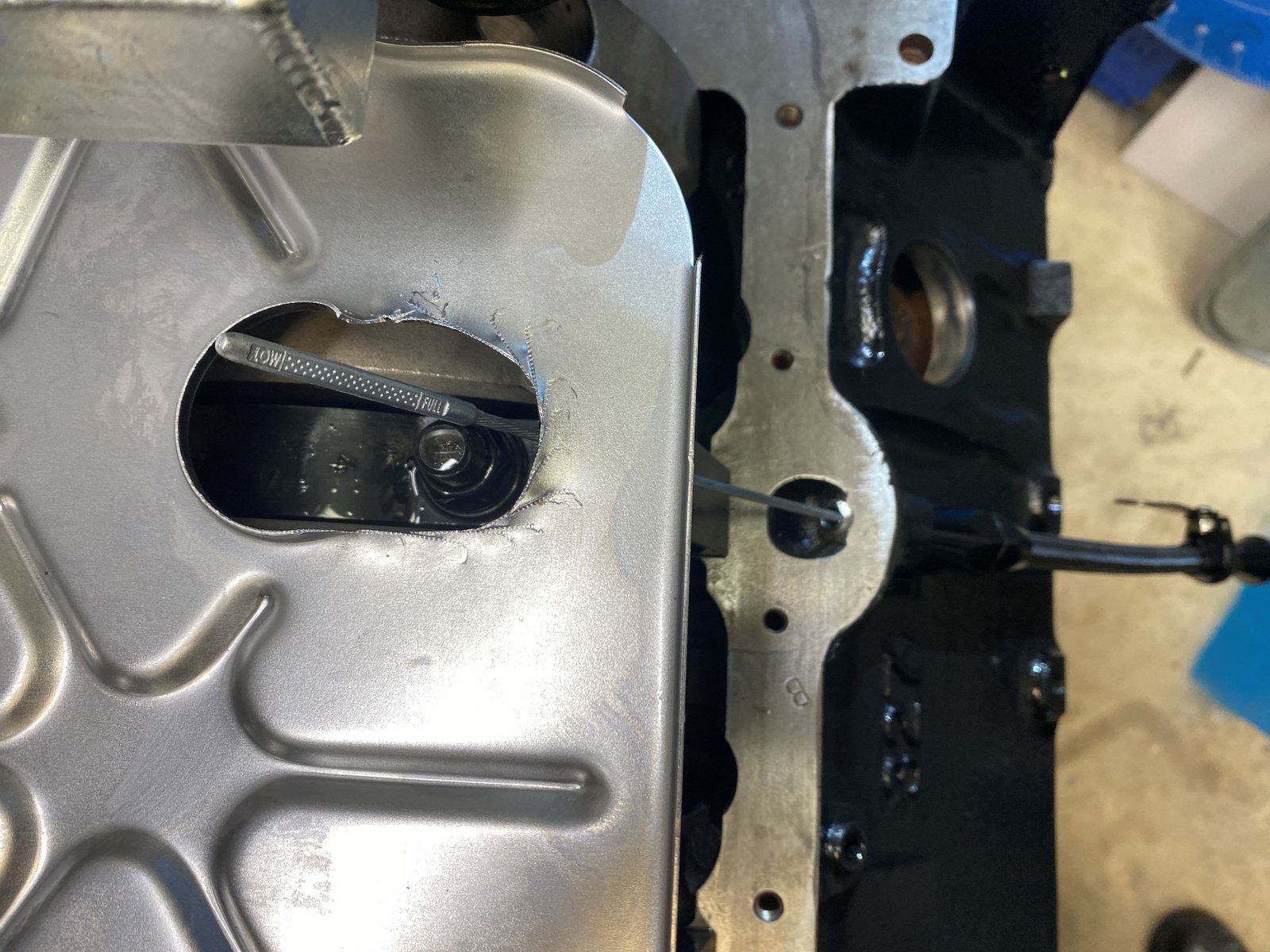
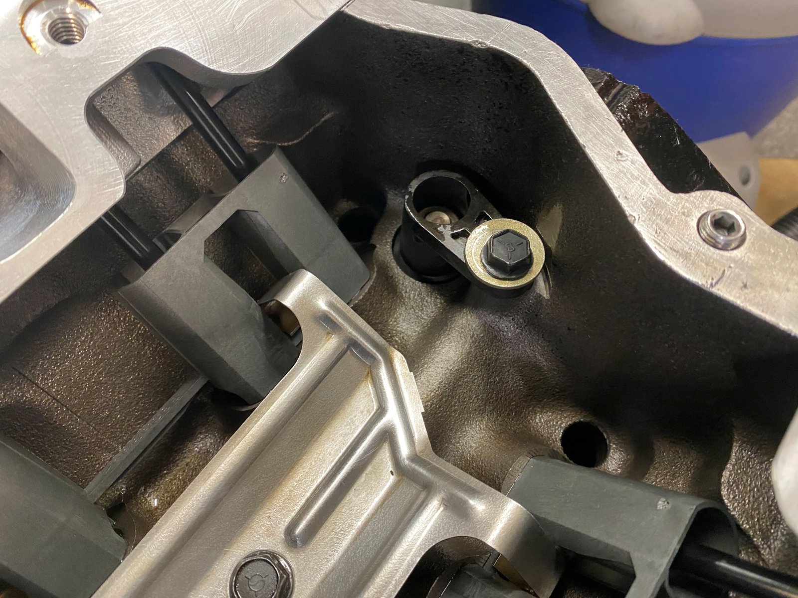
Dip stick and windage tray mods to allow the oil stick to pass
through the windage tray. Also the dip stick tube needs to be
shortened in order for the stick to bend up and over the main cap.
A subtle thing is that the dip stick tube needs to be this short
so that the stick can be removed...make the bend...without getting
snagged.
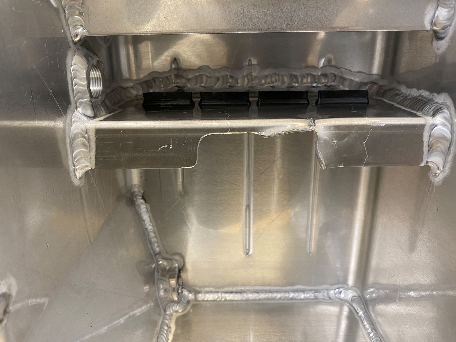
Turns out the pan needed more material removal because the oil dip
stick bumped into this area. All of that was removed by tin
snips and then smoothed with dremmel. Then to the parts washer
for cleaning.
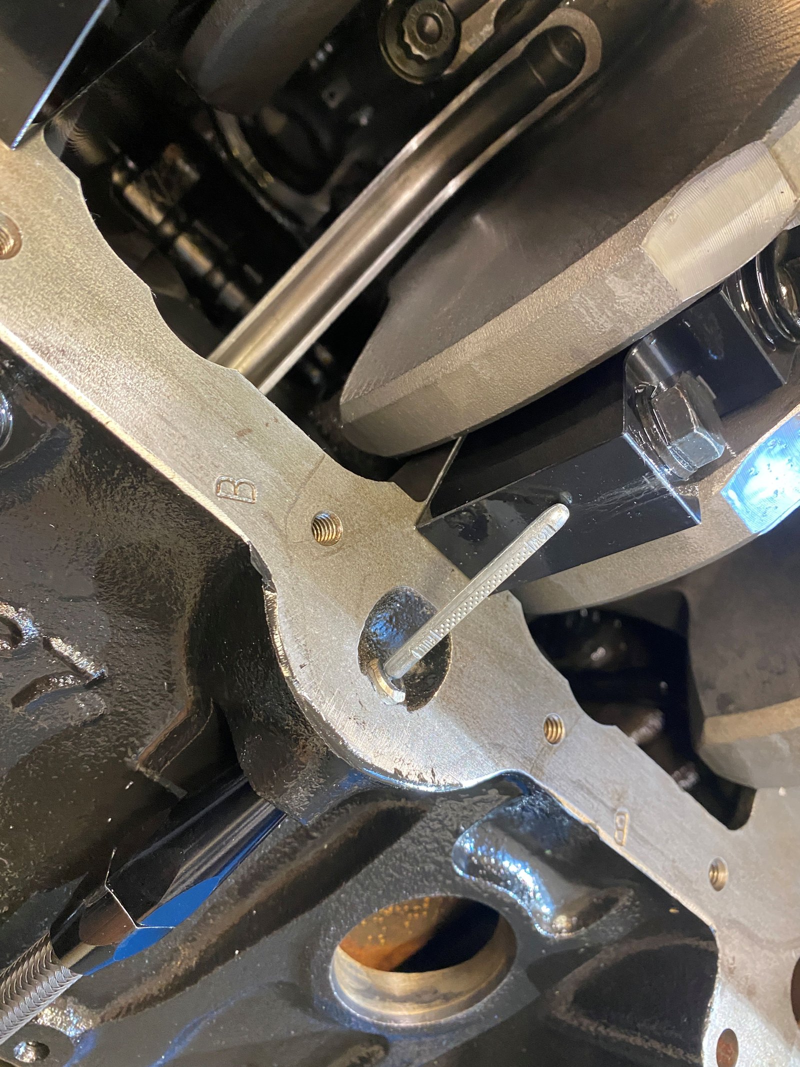
Verified that the stick does not bump into anything and that it
follows the intended path. I've seen more than one 383
stroker with splayed caps have their dip stick tip missing because
it cannot pass the main caps without bending fore or aft and then
the crankshaft hits it.
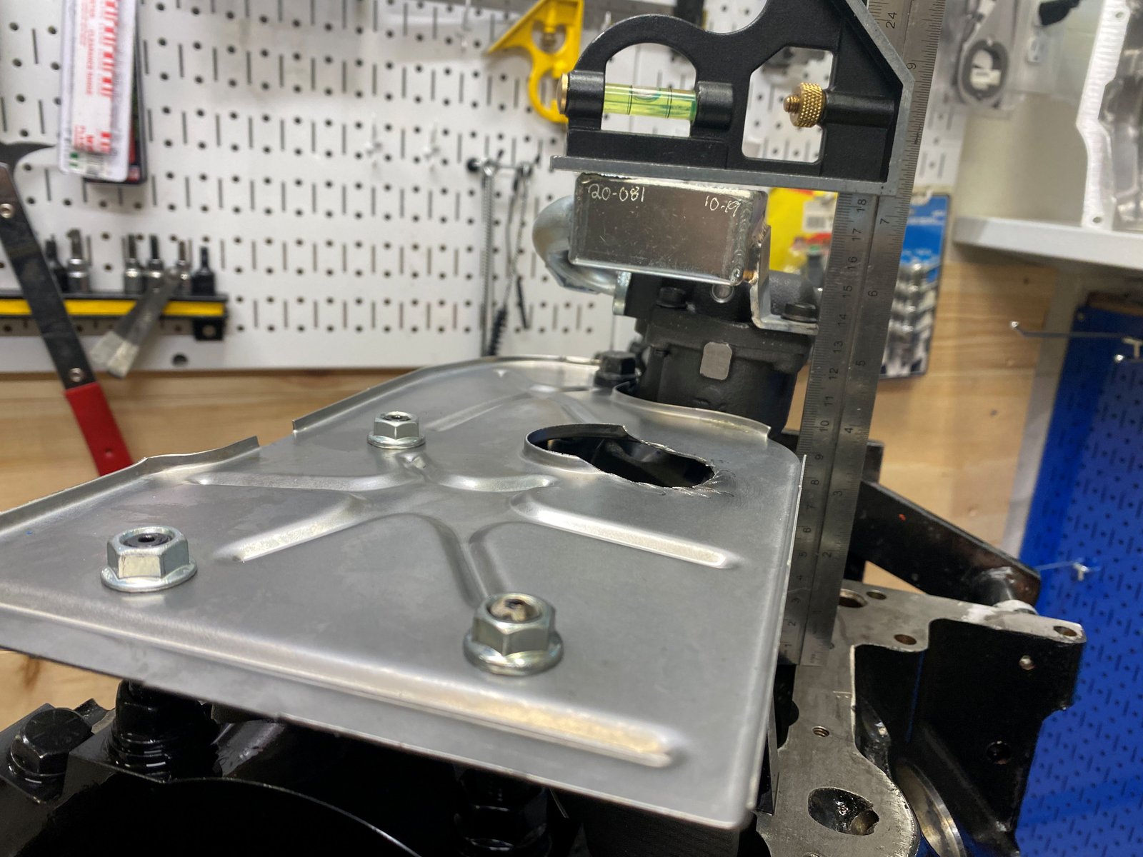
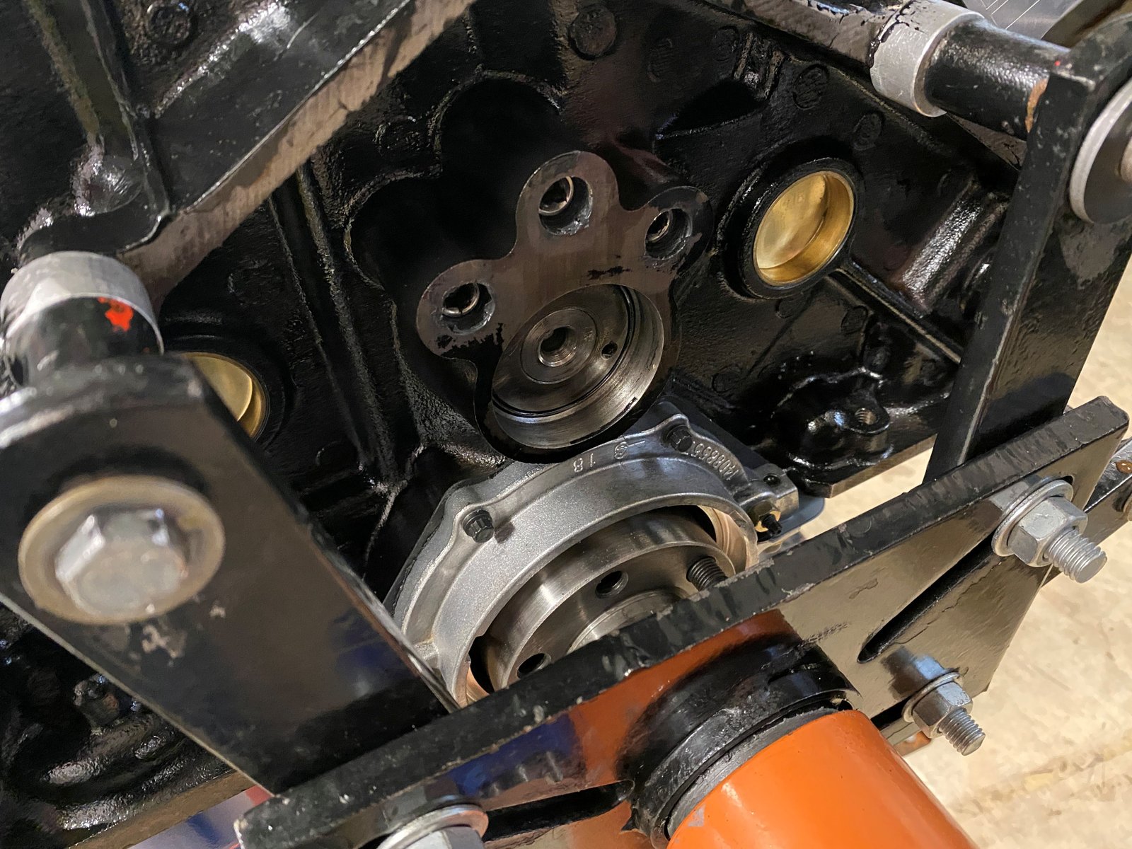
Now centering the rear main seal housing. .003" feeler at
each of 3 centering nubs.
Dennis Staff (the head porter and cam designer) recommended
that I put the cam back to 108* ICL. With this
"one-off" 2-piece timing cover that is easy to do.
No RTV mess and wasted timing cover gasket. I just pulled
the cover and that gives access to everything I need.
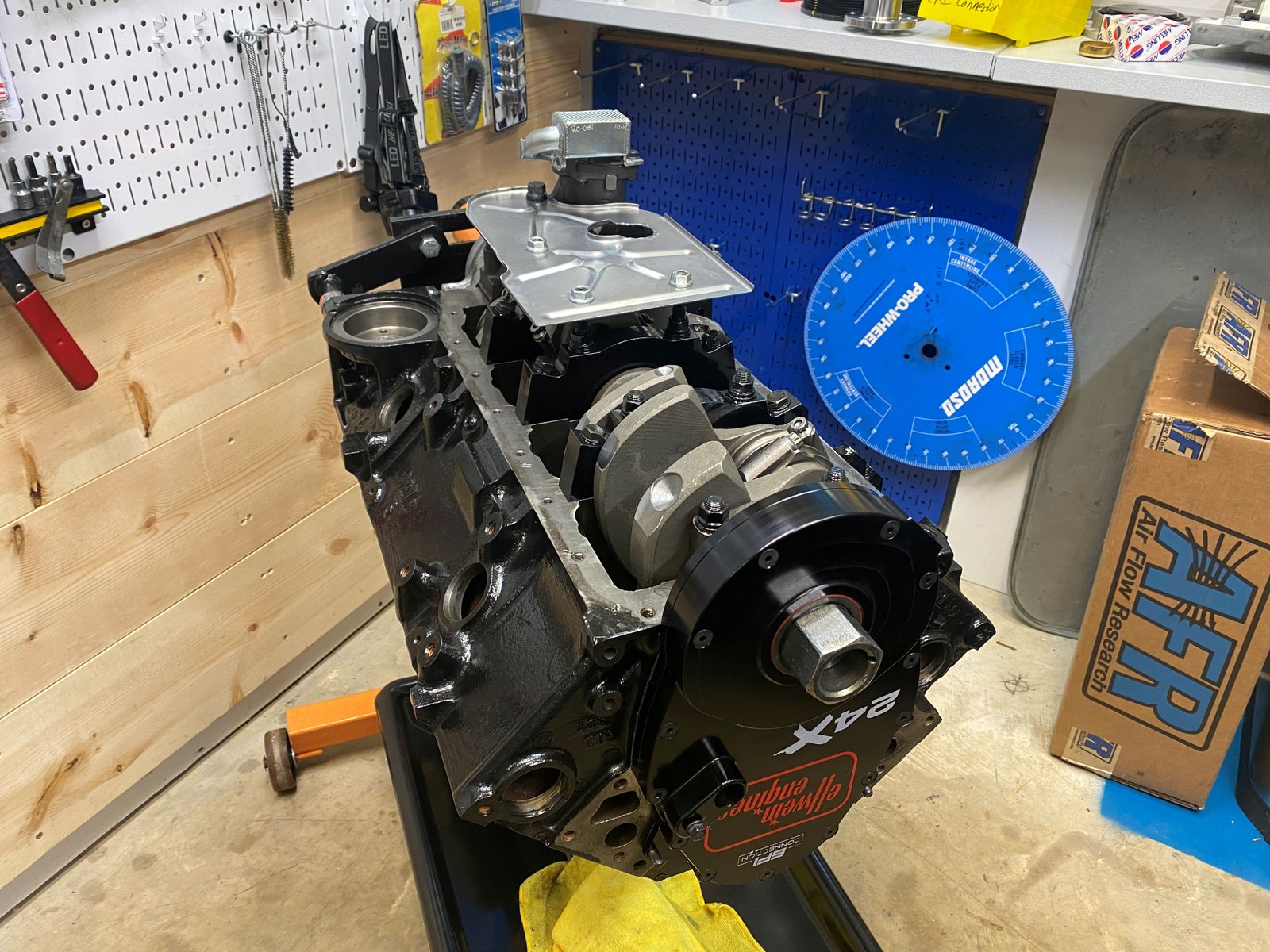
I put the oil pan on temporarily so that I can see if it would
fit well. It does. If this engine were in the car I can
see that even the crank sprocket can be pulled easily.
Timing set set at zero.
Melling 10554ST oil pump now with Canton pickup screen.
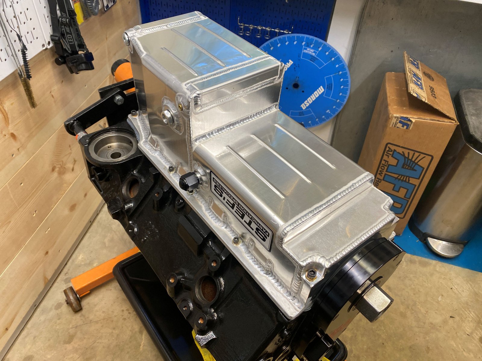
Pickup-to-Pan clearance is a bit on the large side at 5/8". But
that is good when using a deep pan like this 8" deep Stef's
pan.
Pan on with gasket but not RTV'ed yet. I want to check for
clearance. All good.
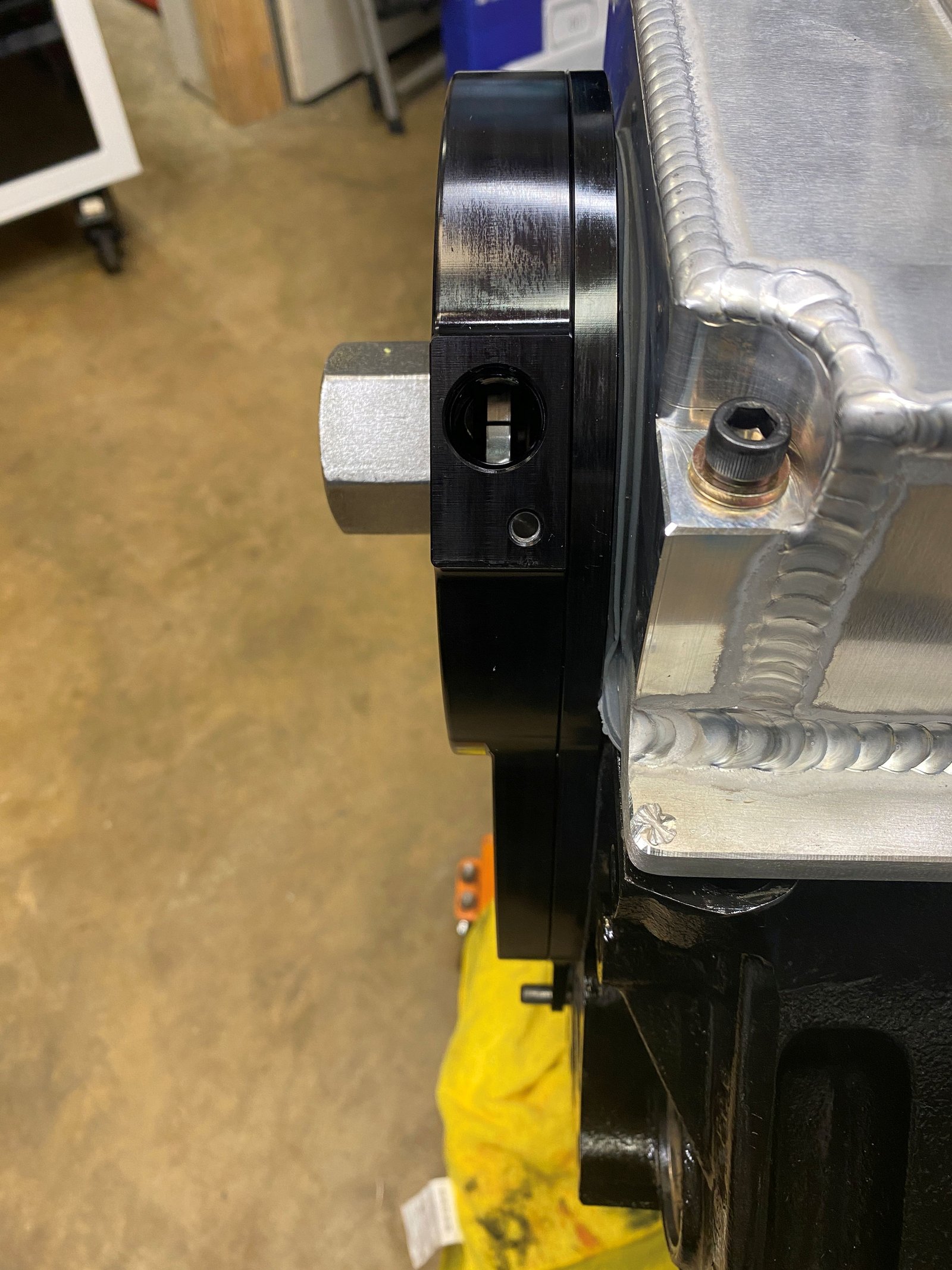
Notice the oil sight glass installed in place of the oil level
switch. This pan was ordered with turbo drain back fittings
too. They won't be used on Mike's car (for now).
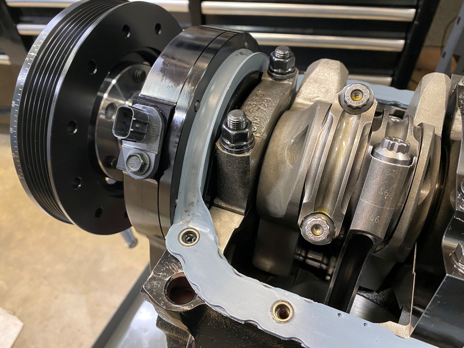
Notice that the reluctor is centered perfectly.
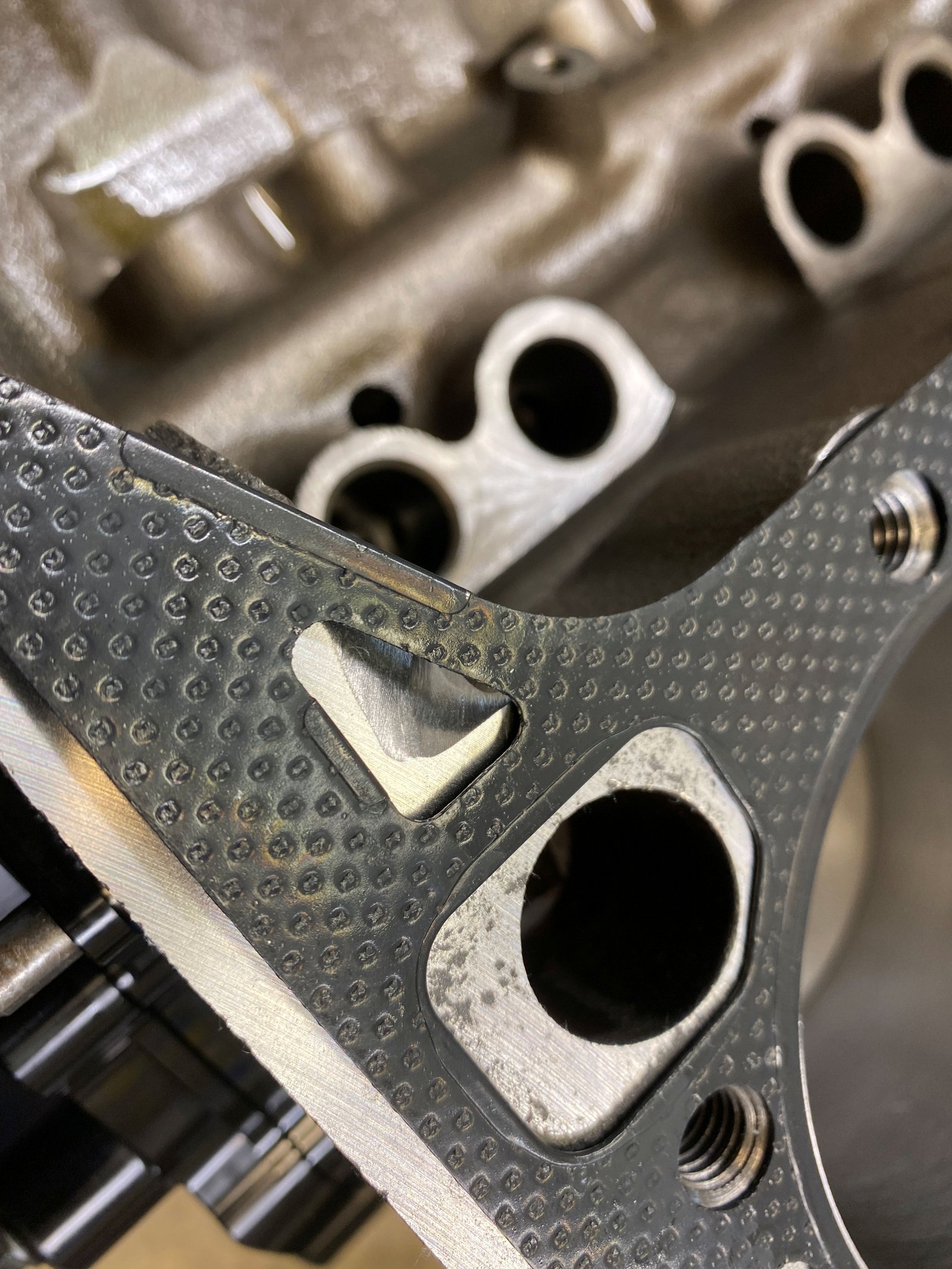
Head gasket is the .026" Mr. Gasket. The photo to
the left is showing the drivers side front where I grind on the
block to give a bit more room for oil drain back.
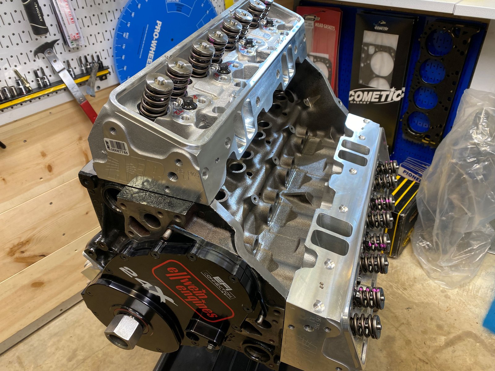
One last look at the AFR heads combustion chamber prior to
installing the head on the block.
ARP head bolts cleaned in the parts washer and then gooped
with thread sealant.
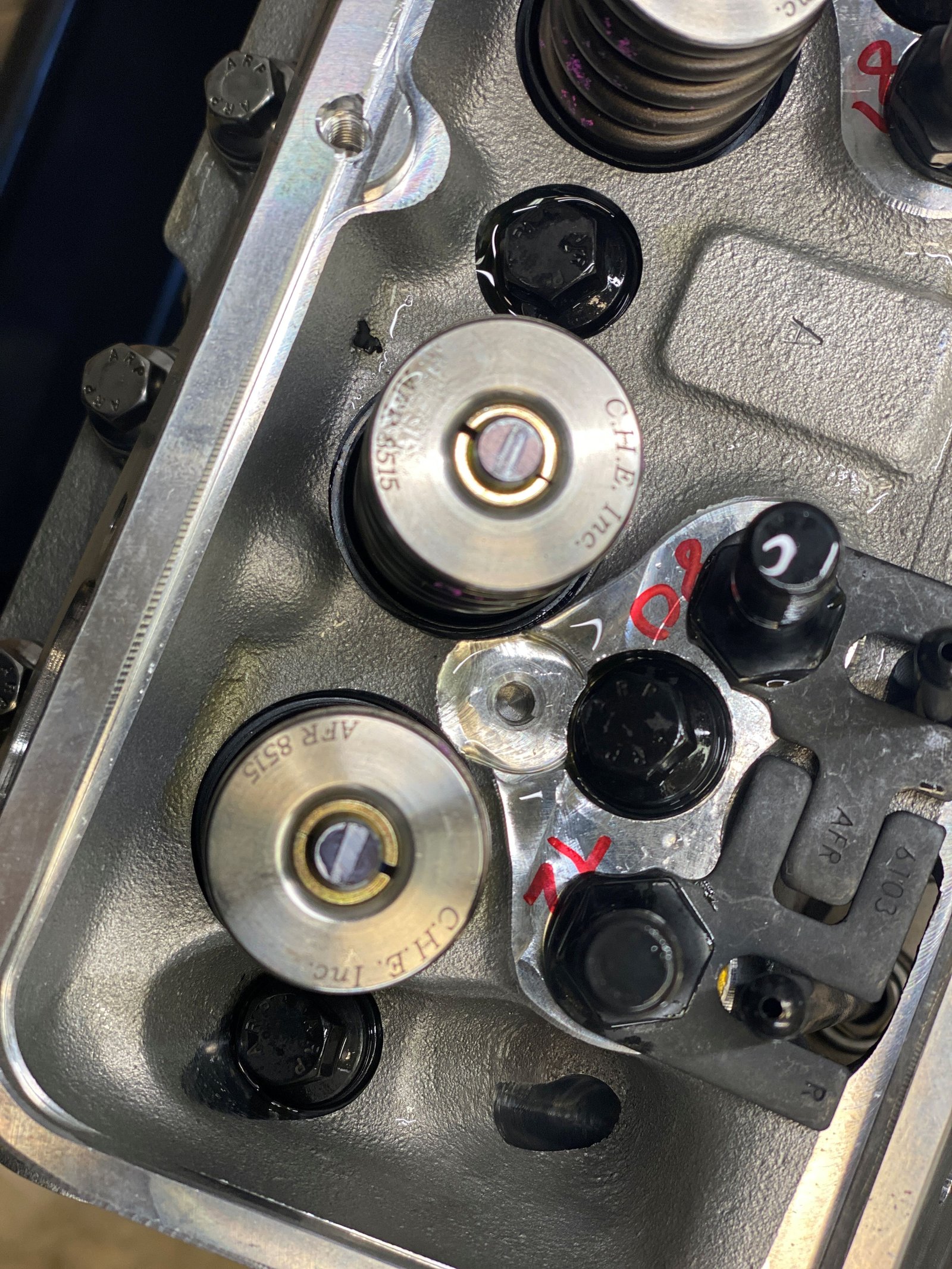
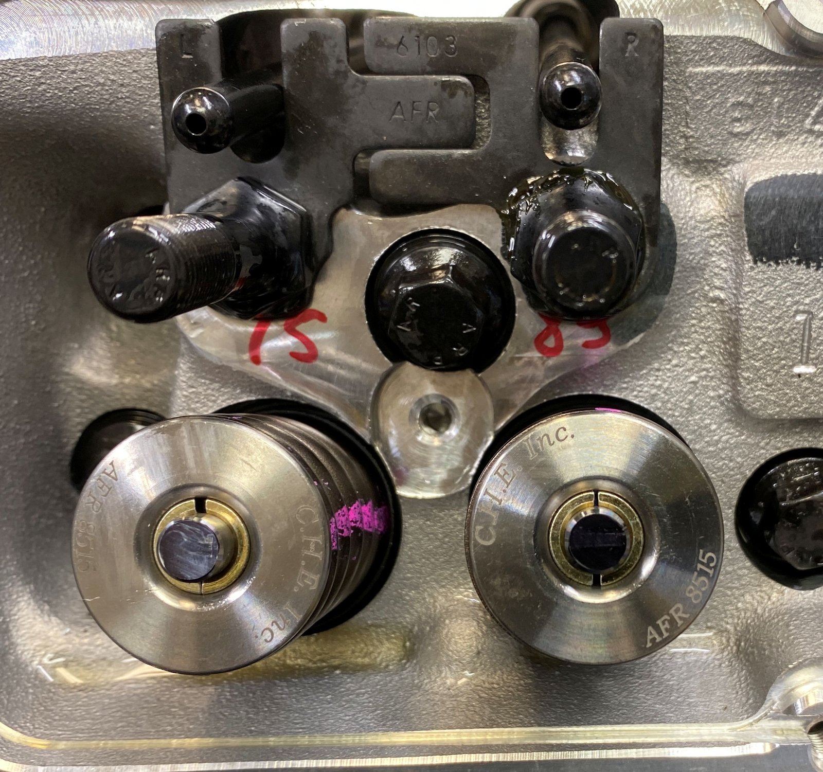
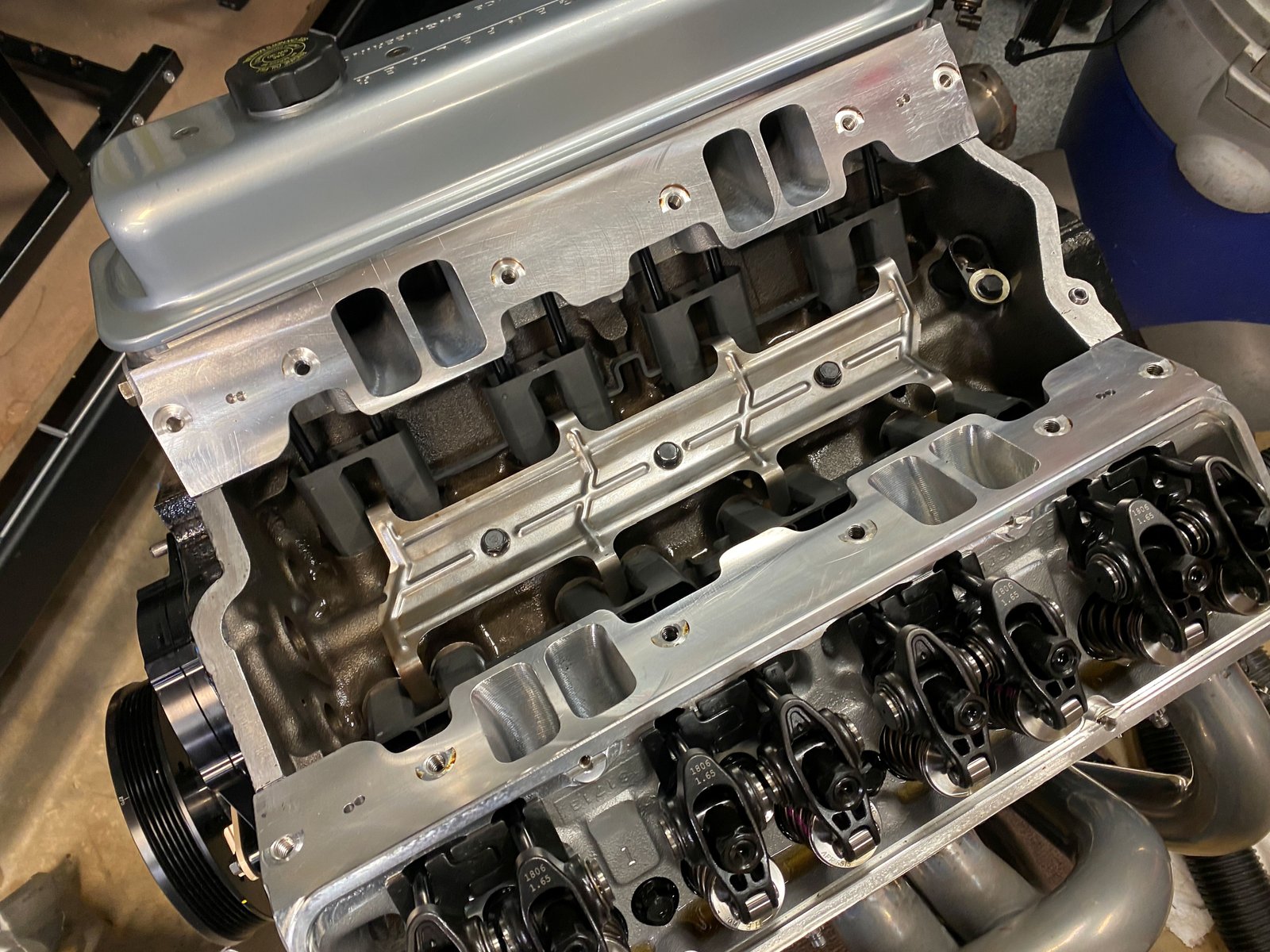
7/16" ARP rocker studs (from AFR). Also washed in
the parts washer and then RTV added to the threads for the ones
that go to the intake runner. The exhaust studs get thread
grease only.
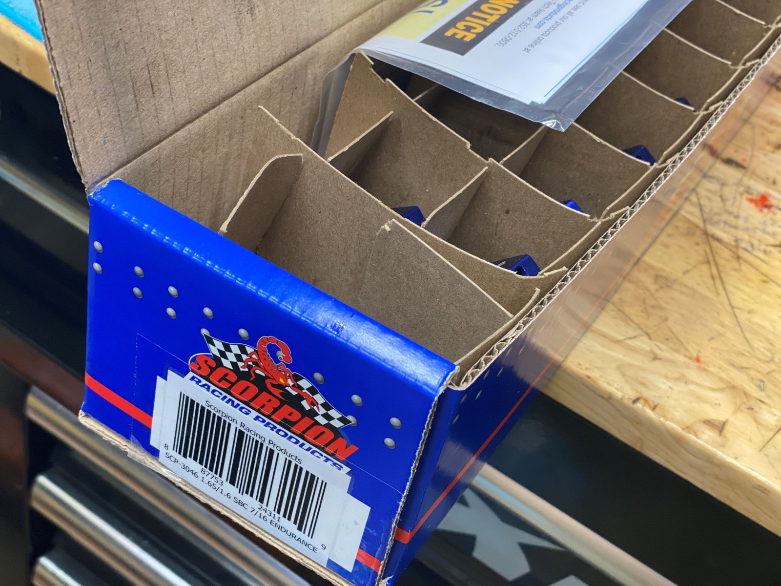
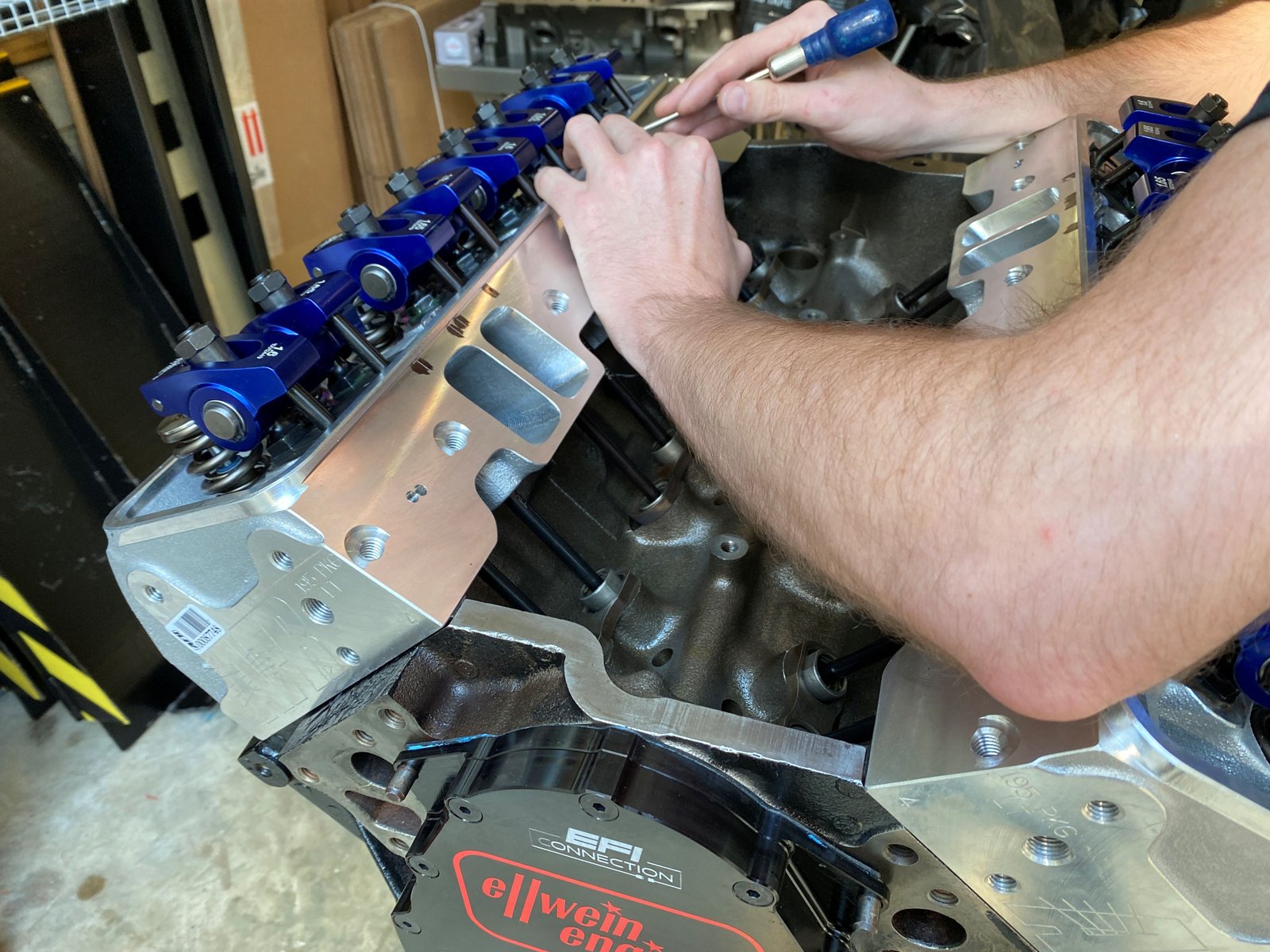
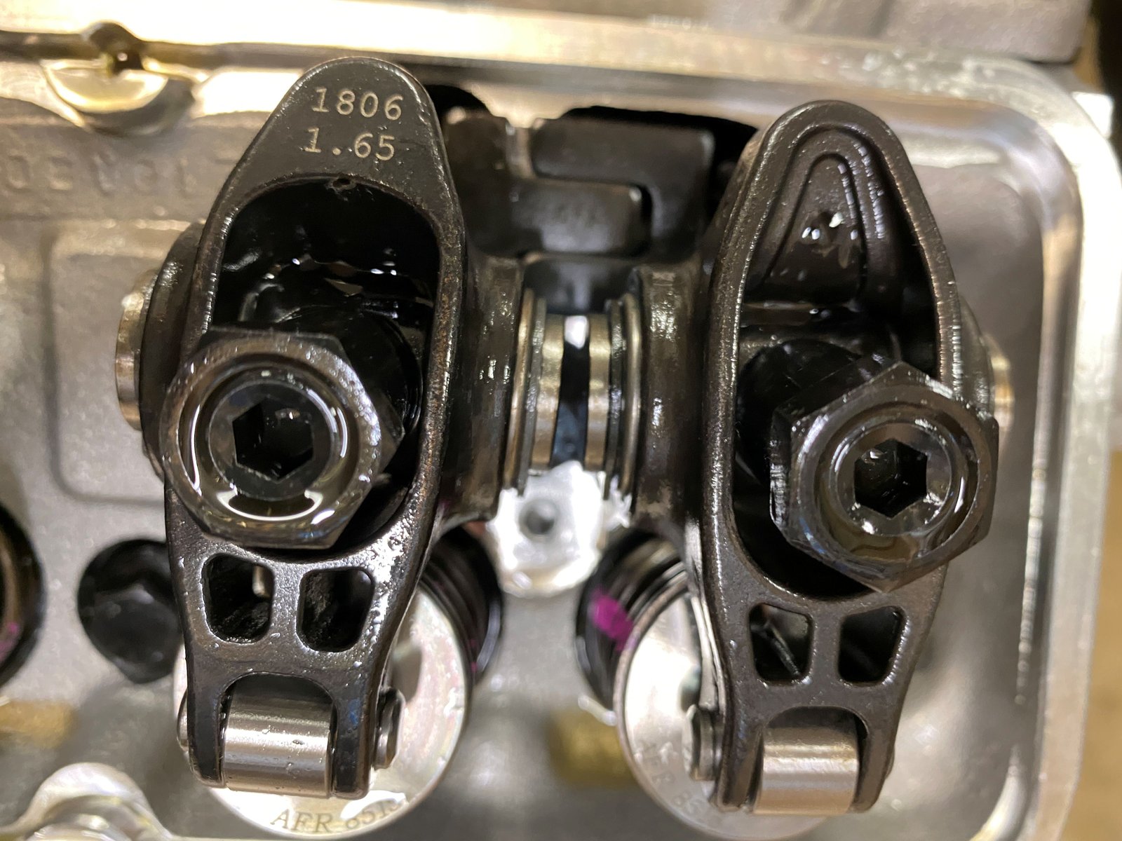
Scorpion rockers in place of the Lunati that I was going to
use. Lunati does not offer 1.65" ratio. These
should be as good as the Lunati. It is a 1.65/1.60" split
set.
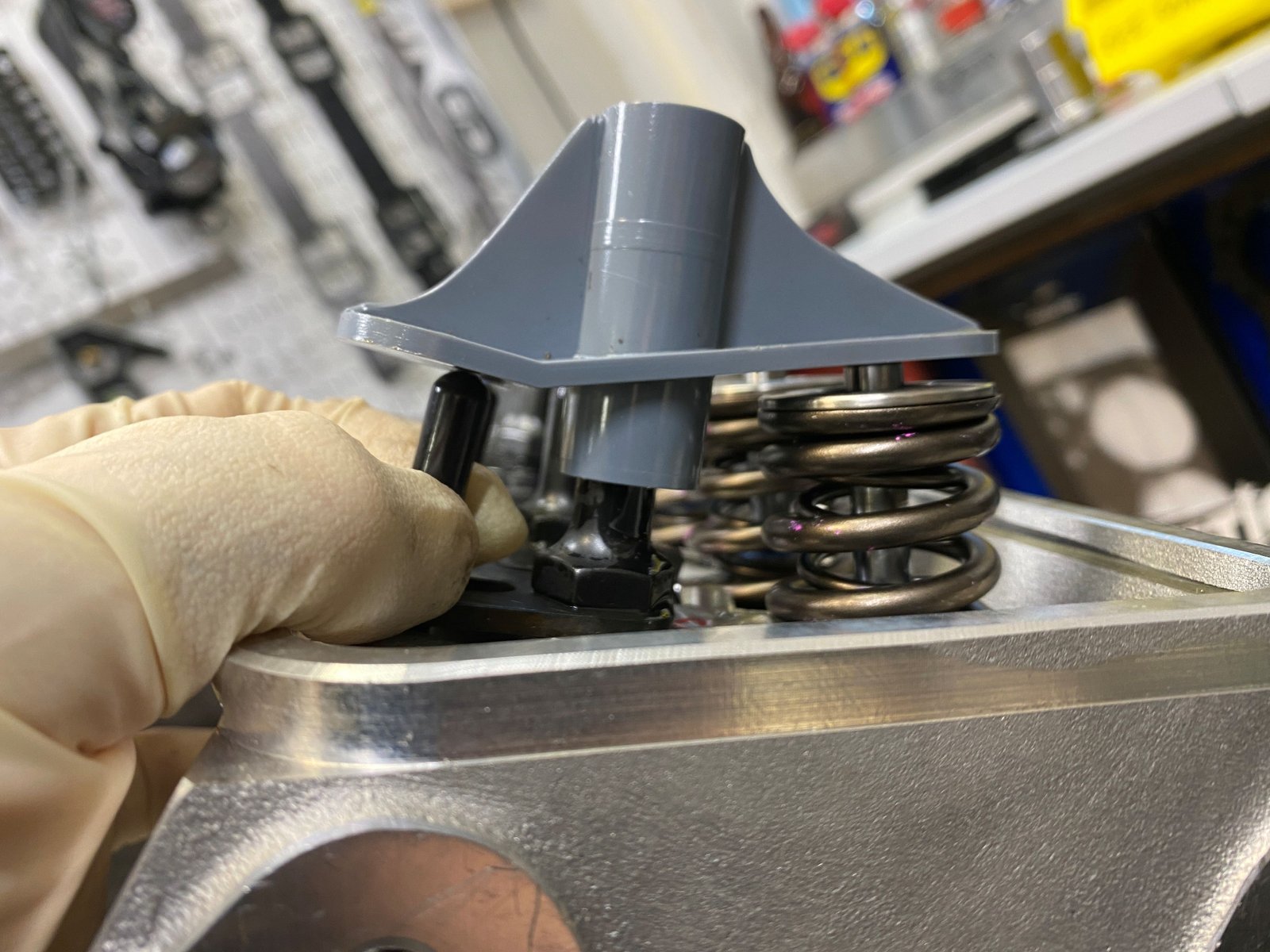
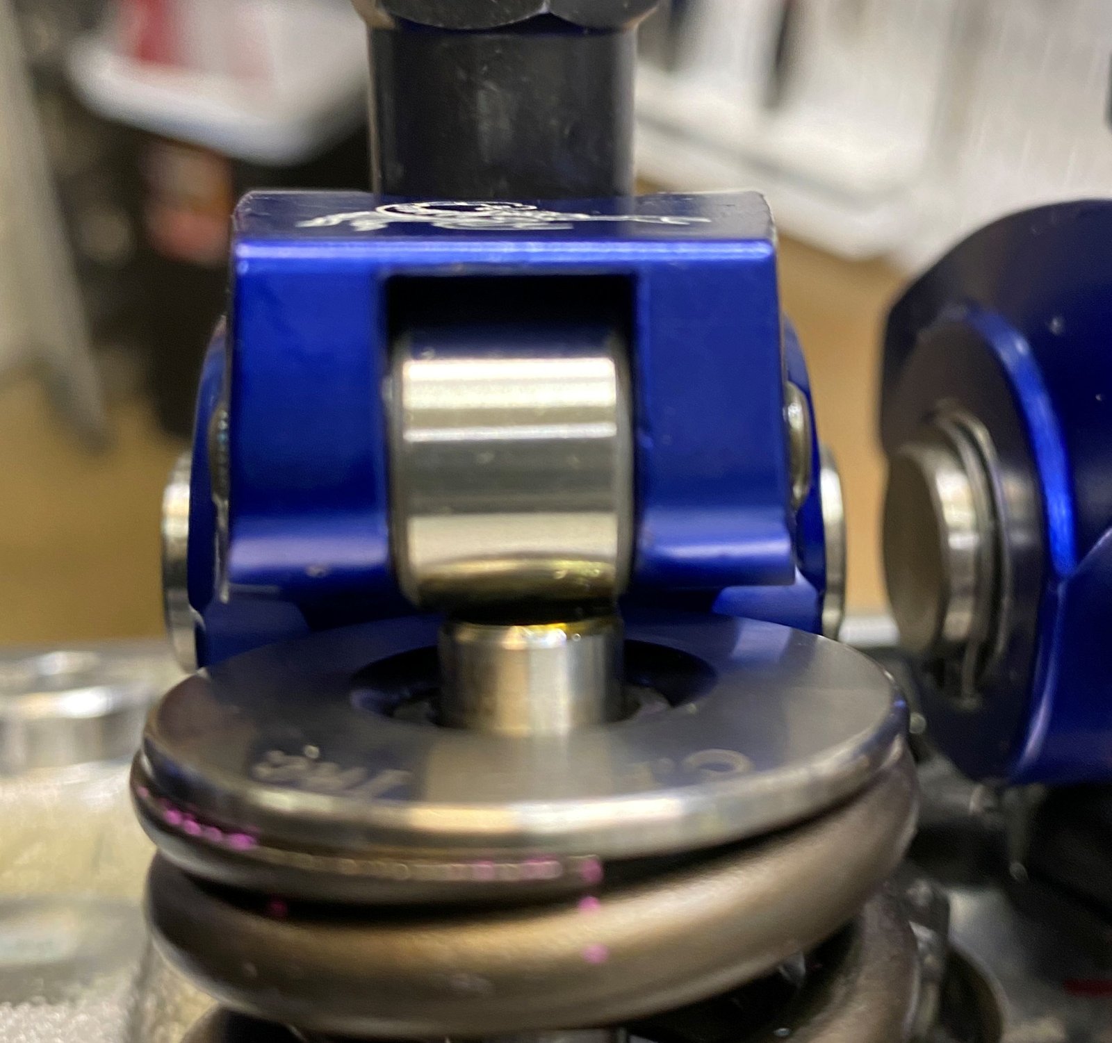
7.200" pushrod mocked up with temporary stock style
hydraulic lifters. The witness mark is pretty good.
Also checked with the geometry tool. 7.200" is the
fit.
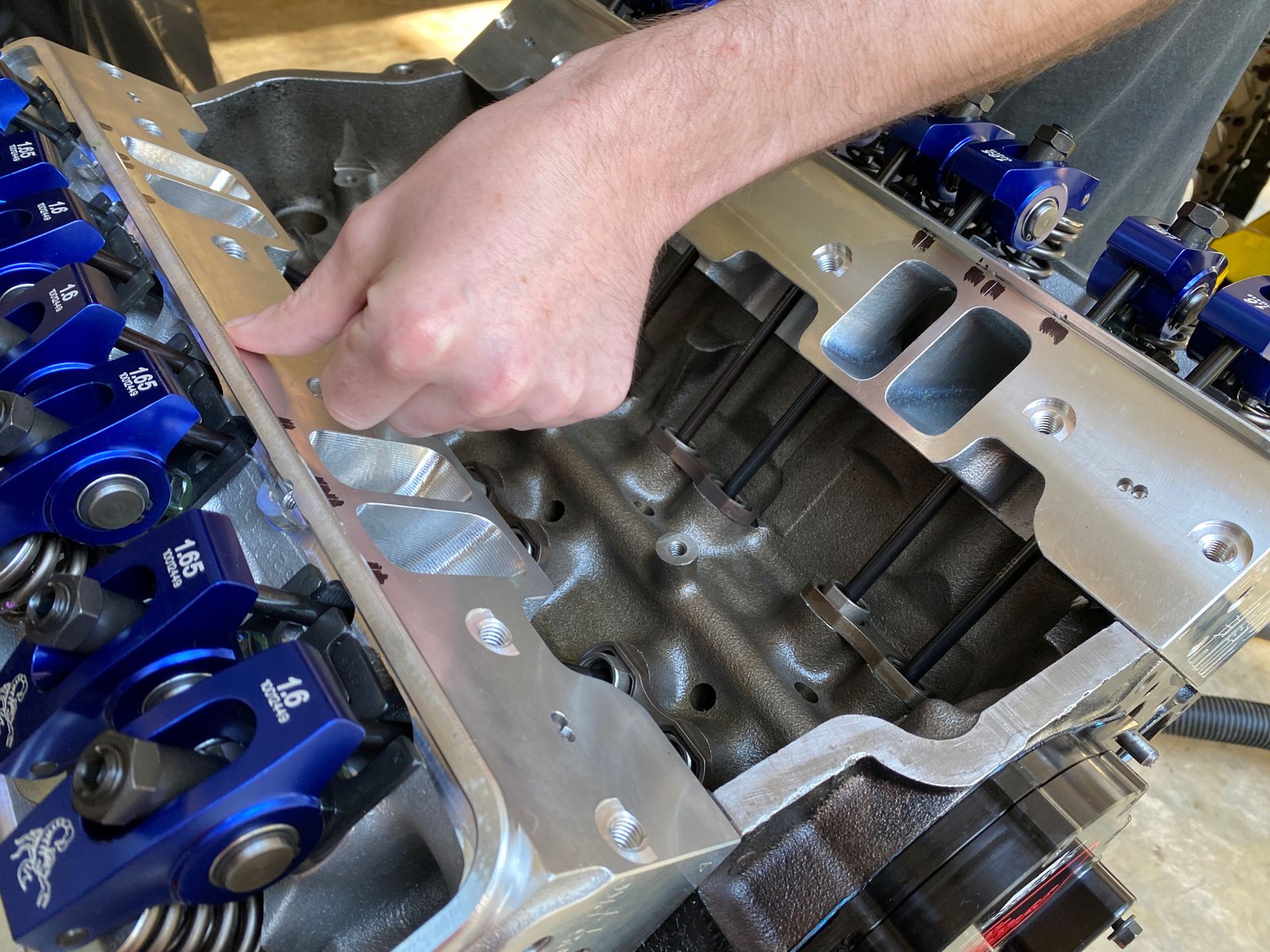
A few spots have the pushrod rubbing the side of the pushrod
hole in the head. And so to keep away from that I have to set
the lifter guide where the rocker tip is just a bit
off-center. See photo to the right.
This is the compromise so that the pushrod does not rub the
cylinder head.
Still waiting for Johnson lifters to arrive but the
pushrod/rocker mockup and test fit is complete with my temporary
set of stock lifters.
7.200" pushrods were too short. 7.250" will be
almost perfect.
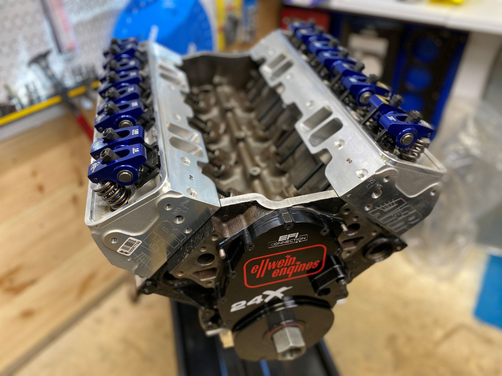
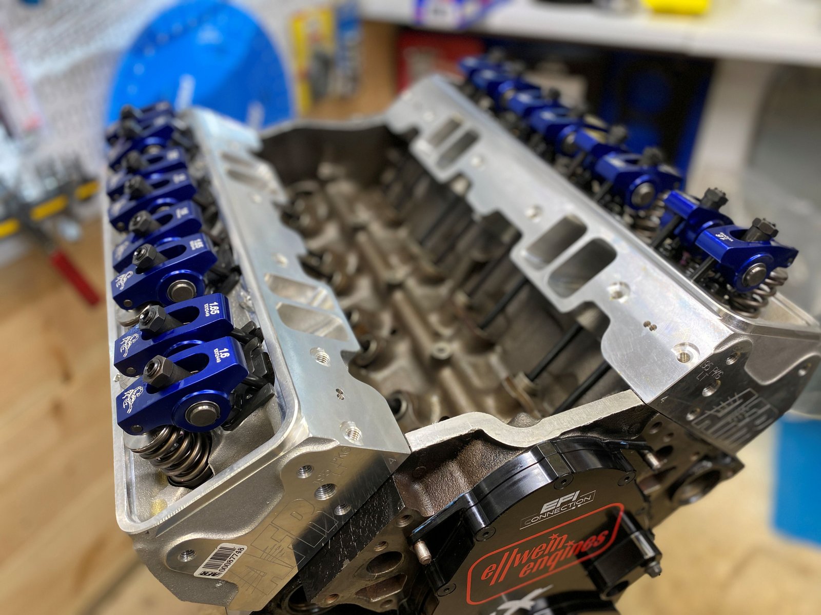
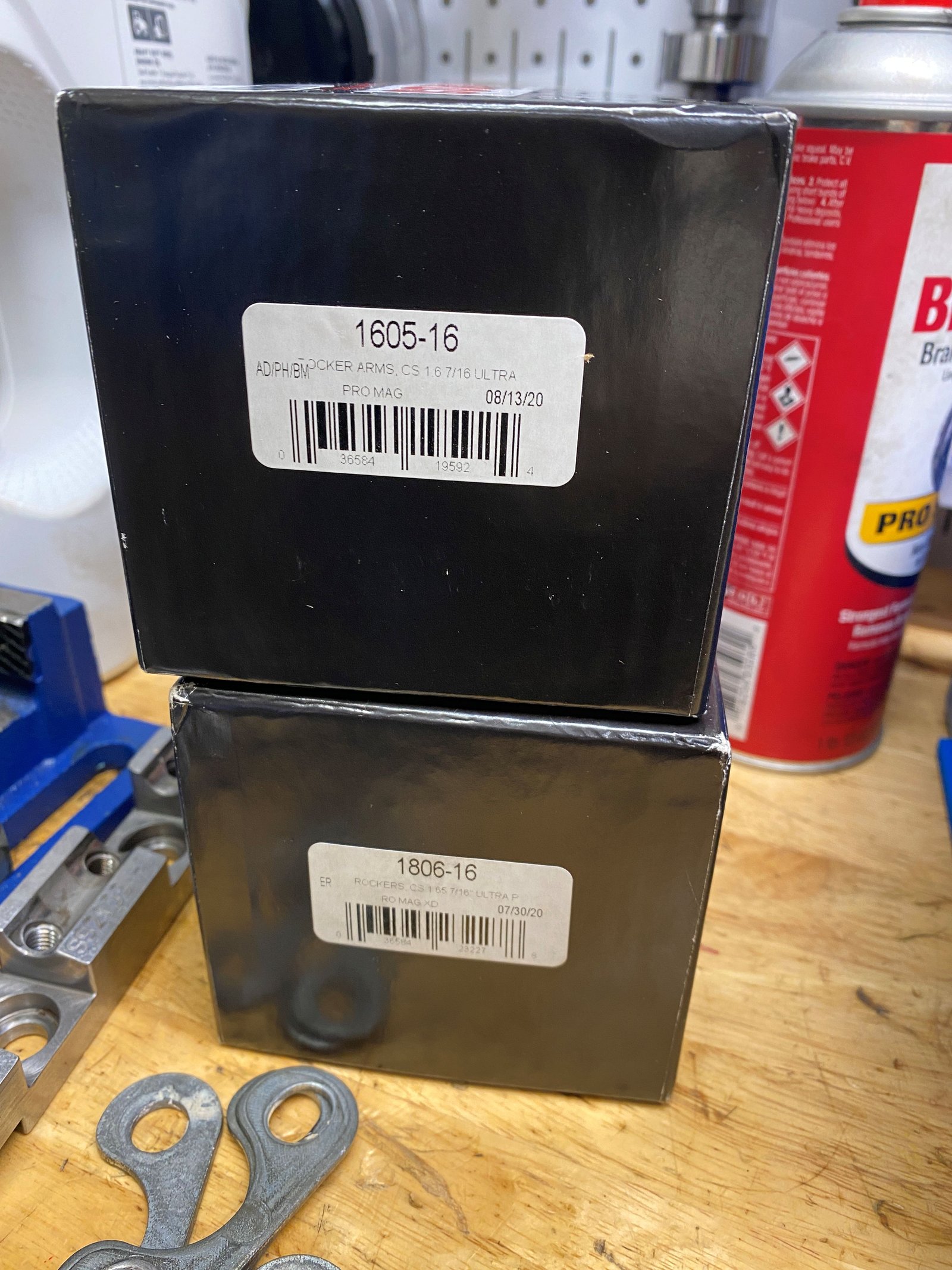
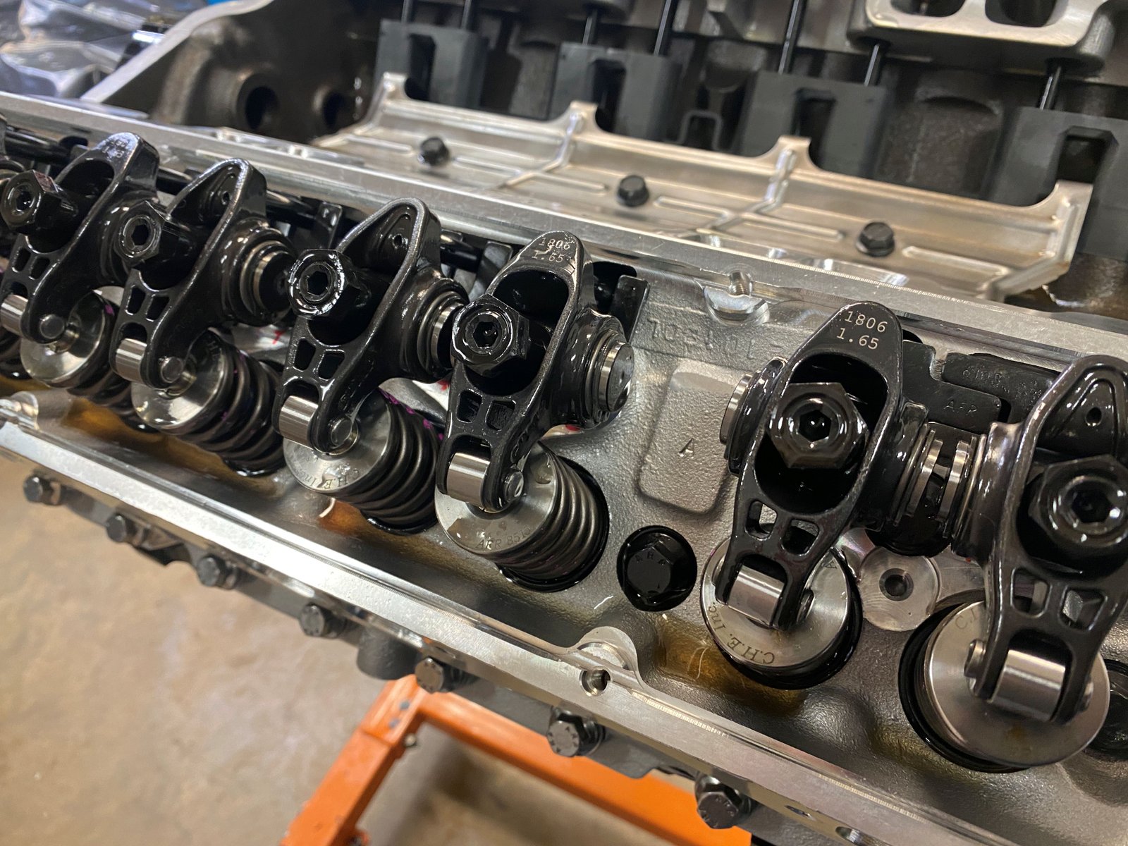
Decided to go with the Comp steel roller rockers. One set is
1.6 Ratio Ultra Pro Magnum and the other set is 1.65 ratio
UltraPro Magnum XD.
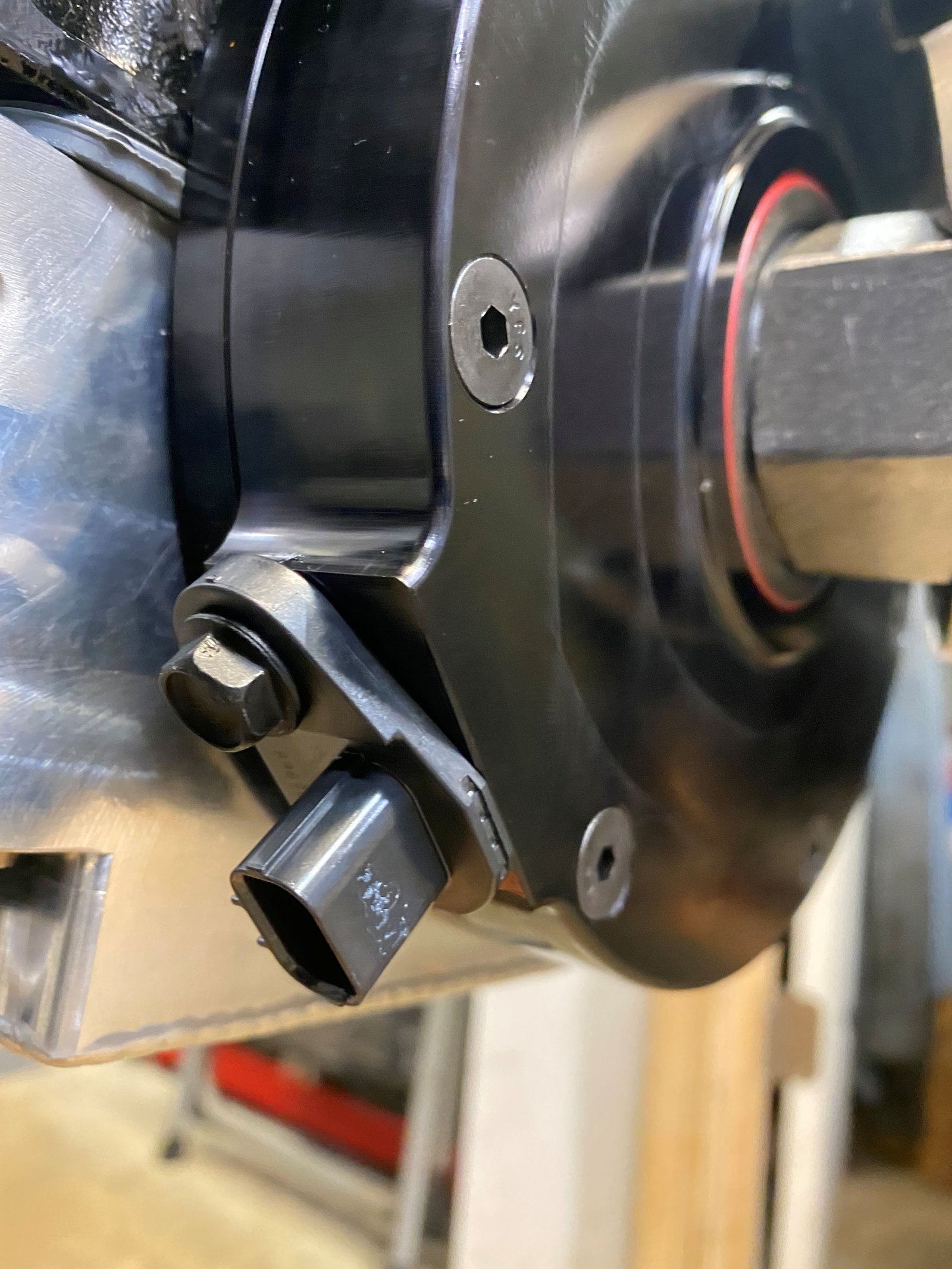
Mike Noonan's 2-piece cover and this nifty crank sensor.
With 7.250" pushrods the rocker tip witness mark is good.
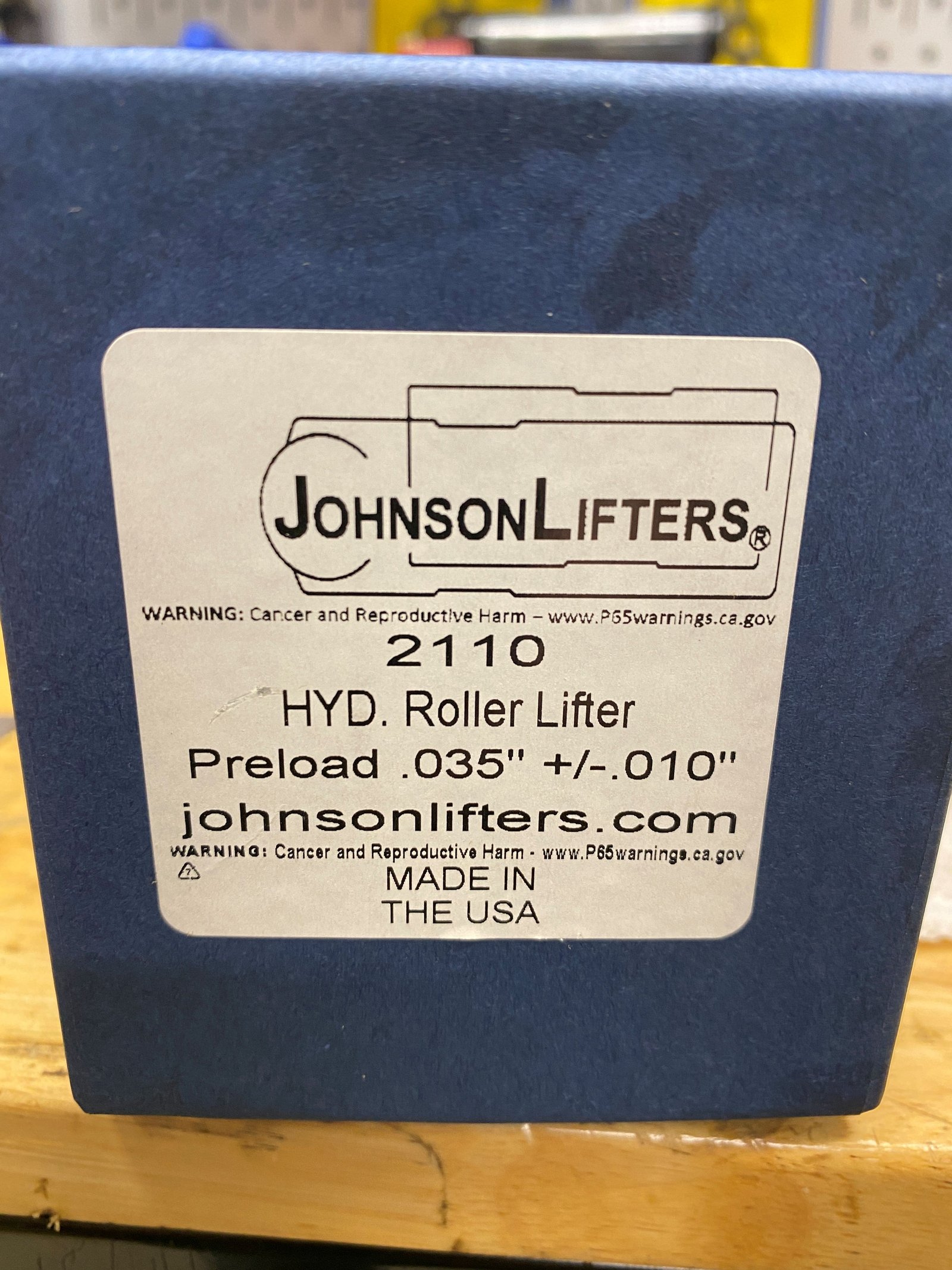
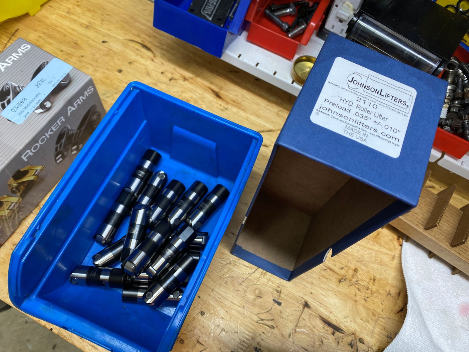
Johnson lifters. Stock style.
Valve train set up. The preload is 1/4" turn then a
bit more to tighten the polylok.
Press on of the crankshaft hub with my threaded rod.
Temporary valve covers. I need to clearance the inside of
the Mike's valve covers to fit over the Pro Magnum rockers.
I made sure to RTV the "top" side of the oil pan
gasket. I don't RTV the "bottom" side (oil pan
side). If the pan leaks oil then and only then will I RTV
the bottom surface of the gasket.
Rear plugs need to be installed and the rear main seal.
Also need to make a timing pointer....
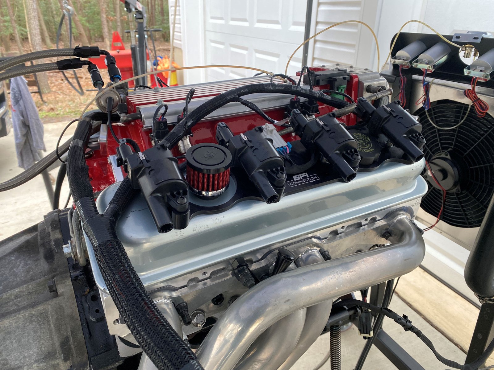
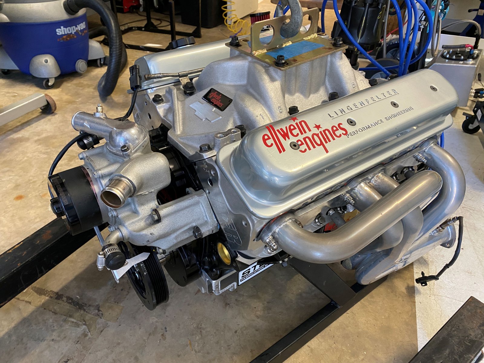
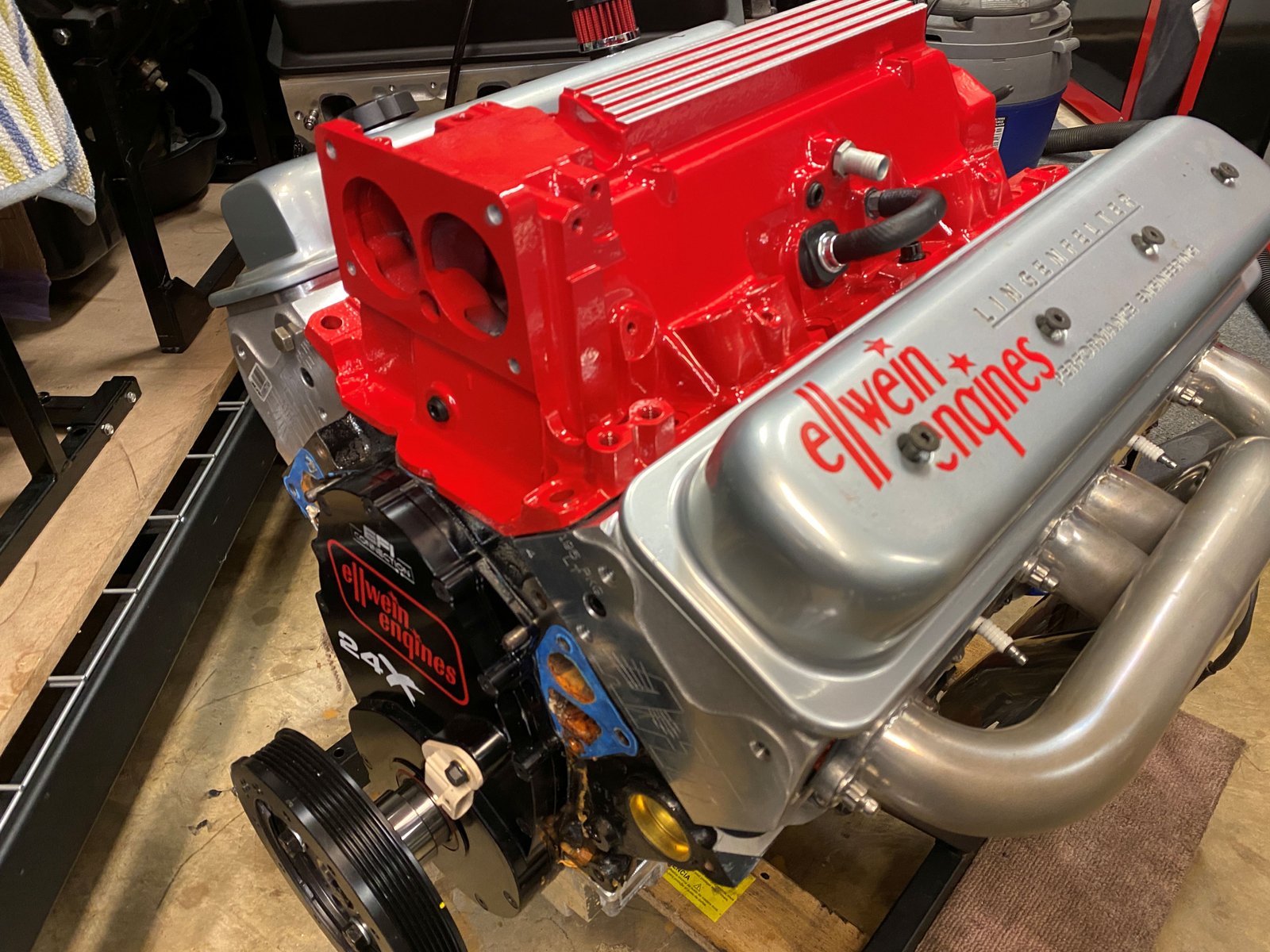
Why the carburetor manifold?
I'm taking her to the engine dyno soon while the EFI intake is
being ported. After the carb dyno we will be doing the EFI
dyno.
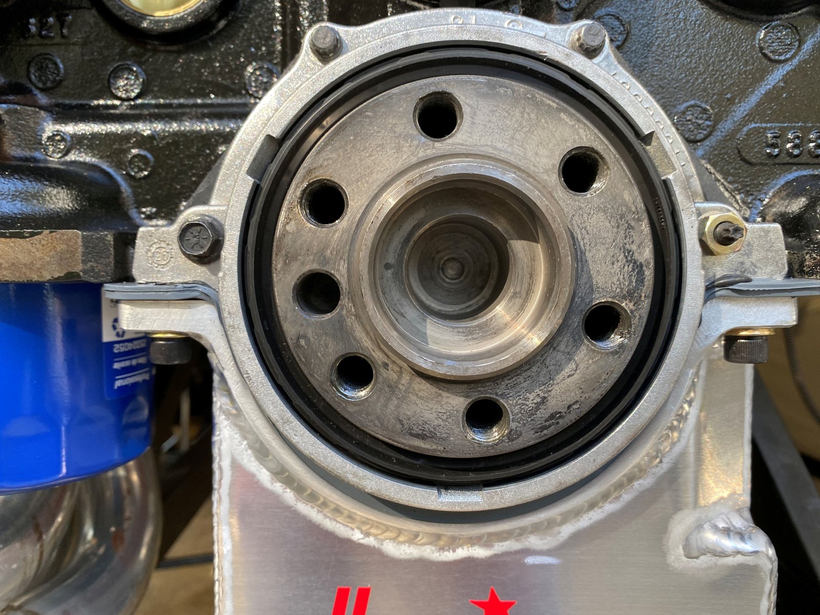
Rear main seal on.
Dennis Staff of Fast-Cat
Porting Service. He drove over last week to make sure he
had accurate measurements for the intake manifold port
matching. The heads should be on the engine in order to get
the most accurate (assurance) that the ports will line up.
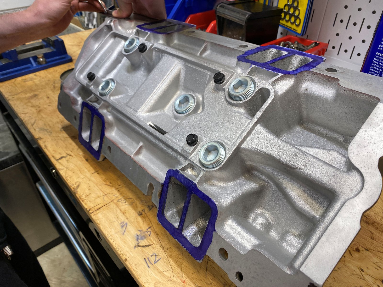
This is the 1st time I've seen the process. Dennis marks
the outline of the head ports up near the valve cover rail so that
he can see the marks when he puts the intake manifold on.
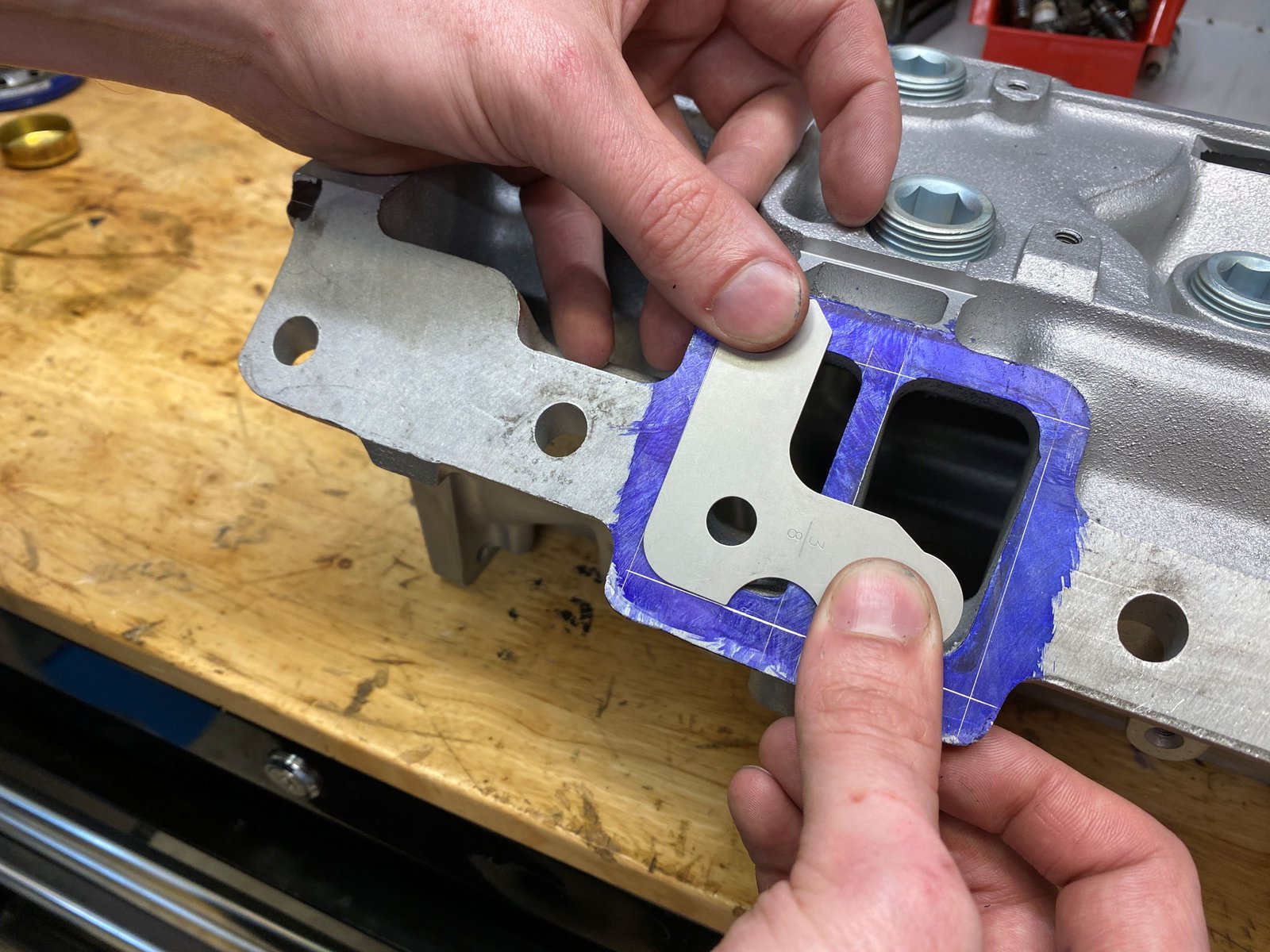
Then with the manifold on (and shims acting as gaskets of
exact thickness) he can transfer the marks to the intake manifold
ports.
And more measuring...
And port size transferring from head to intake.
This is the exact corner radius of the cylinder head port.
Here is a photo I missed a few days back when inserting into
the build page. Why am I a fan of the Johnson lifter when it
cost more that $400 for the set? They are 100% QA tested for
bleed-off and they are 100% USA in material and workmanship AND
they are always in stock. I'm getting them from Brian Tooley
Racing right now.
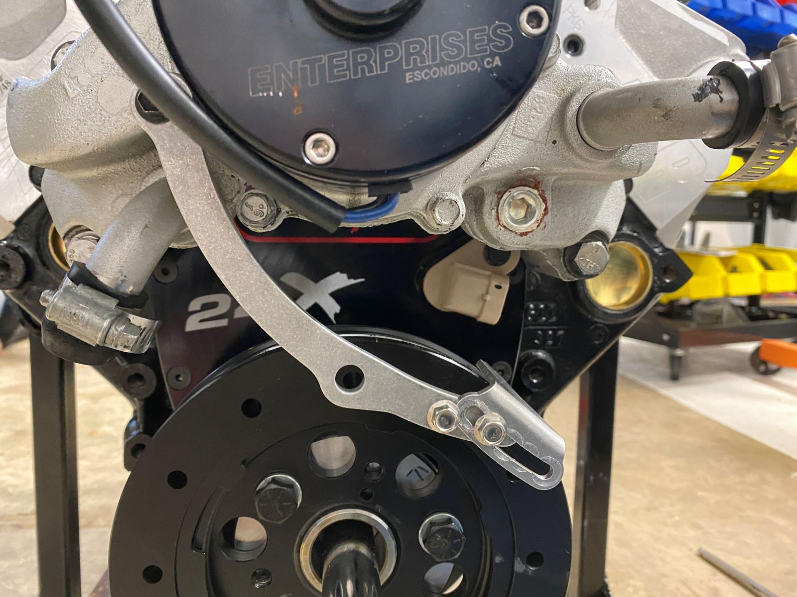
Make shift timing pointer.
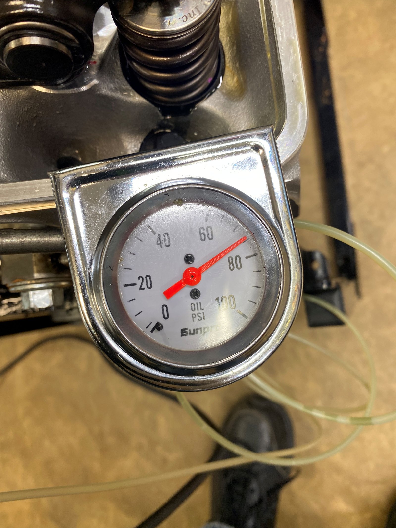
Oil pressure test with drill
Dyno valve covers
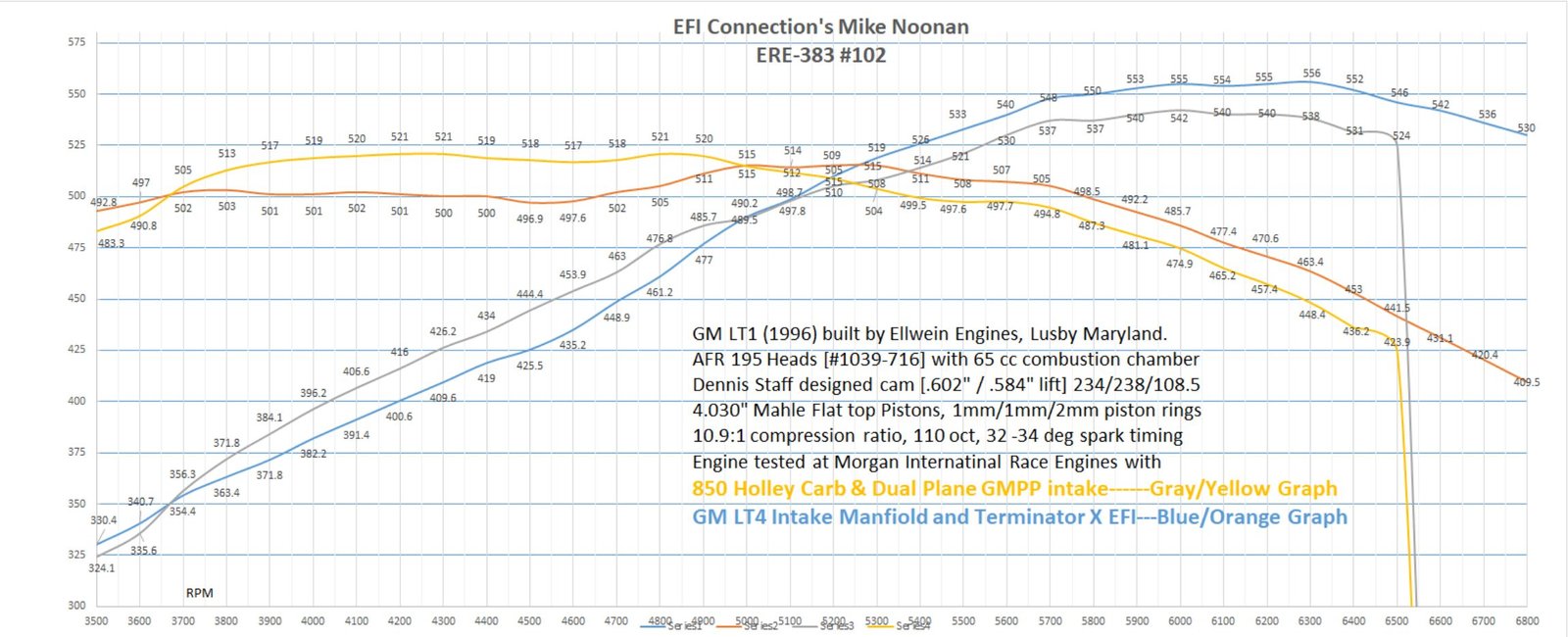
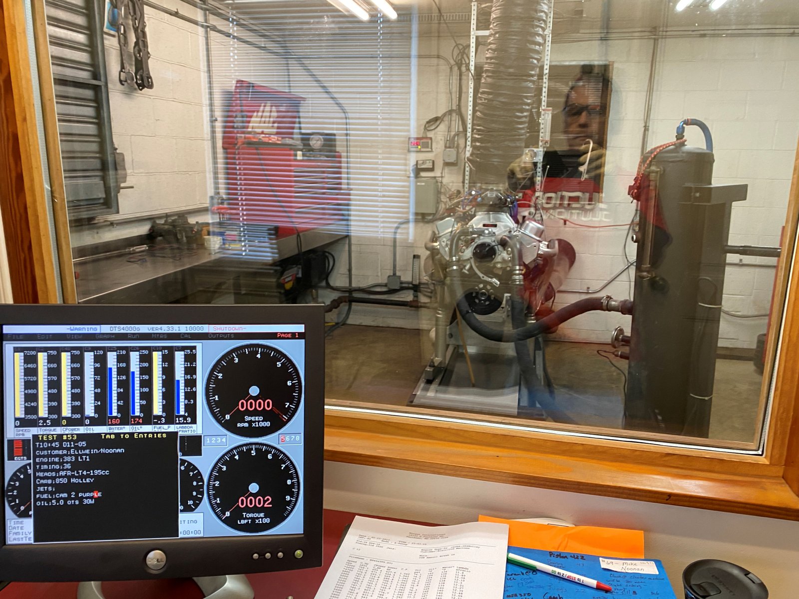
Jim Morgan of Morgan International
Click on the dyno sheet for a
link to the dyno video
After dyno rear main seal check. All dry.
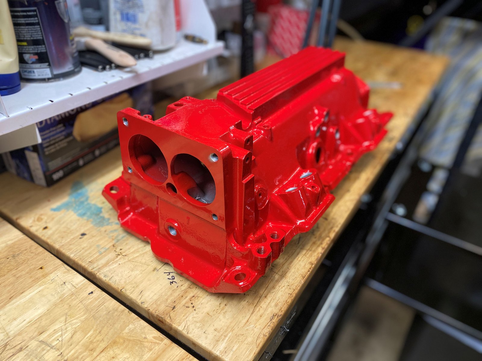
EFI intake manifold is back from porting and power coating
The fins will be machined to remove
the powder coating and then the engine will be set up for EFI dyno
testing. Soon.
Photos below are of the EFI dyno
set up beginning with installing the intake manifold and quick
test on the engine test stand, (prior to actual engine dyno).
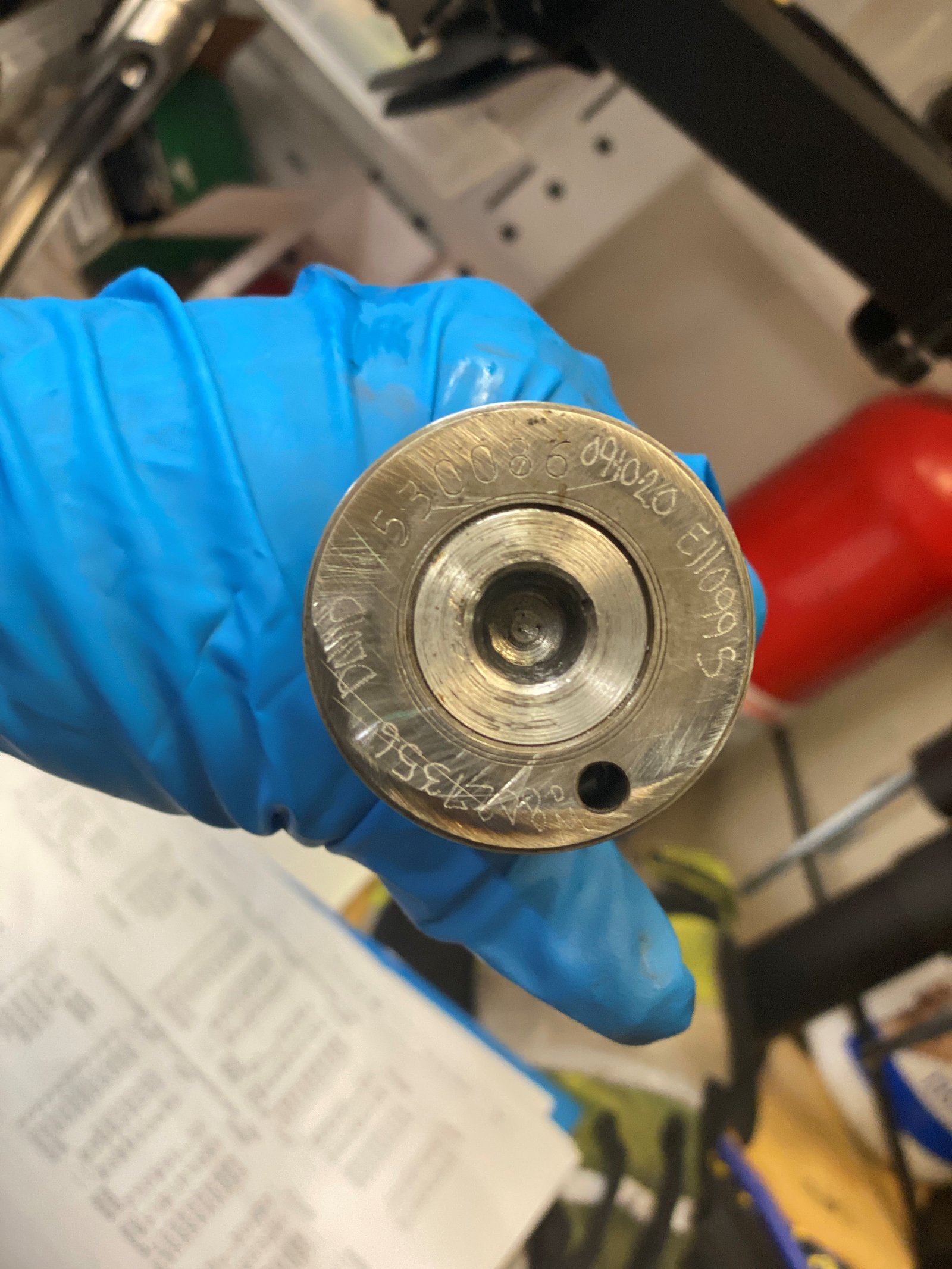
Oil pump drive gear. This is a used core with a new
gear. I torque to 20ft-lb and usually use a washer to spread
the load which keeps the tab from cracking.
Cleaned up from the carburetor manifold RTV. It is a
tedious and careful process so that dirt does not get into the
engine.
After cleaning the intake the core plugs are installed.
The intake was powder coated and then the top fins were machined to
remove the coating. It looks great.
Here I have simply set the manifold on the engine while I
install all the various fittings. The powder coating still
needs to be removed from the sealing surfaces (Throttle body and
head/intake flange).
Looks good doesn't it? I'm bummed about the dyno rusty
water stains. It should clean up but in gets into the cracks
and crevices and oil pan flange.
All cleaned up. I used a very coarse wire brush on a
drill. This photo is taken after SafetyKleen and brake clean and
air nozzle dry.
Notice the heads are NOT port matched to the LT4 GMPP 777
gasket. But the intake manifold is port matched to the
heads.
EFI Connection Holley harness. I love it!
Happy to see things like this...fuel pressure and oil pressure
sensor terminals.