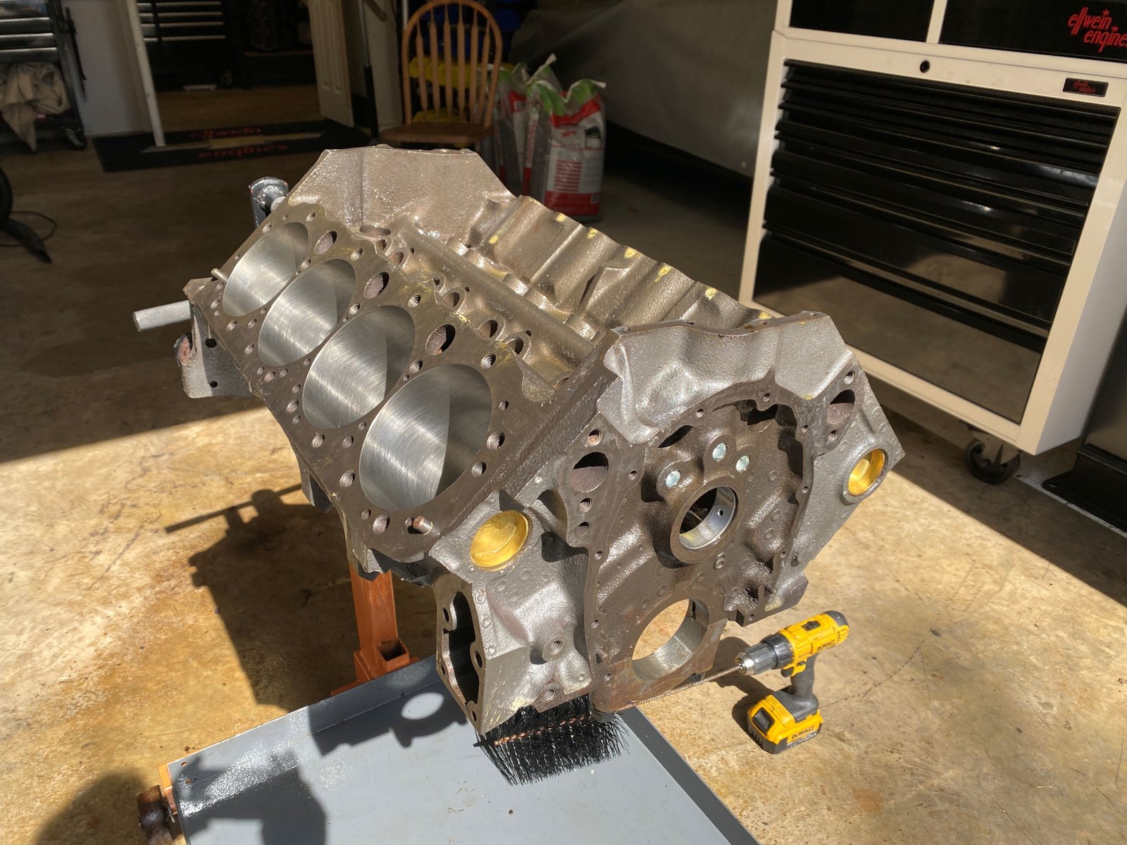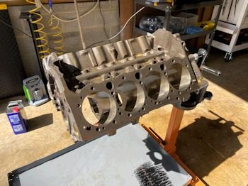
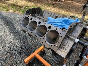
The block has been fully machined prior to arrival at my
shop. It has a lot of anti-rust wax on it.
|

Now just have to give the block a good cleaning. |
I started with WD40
|
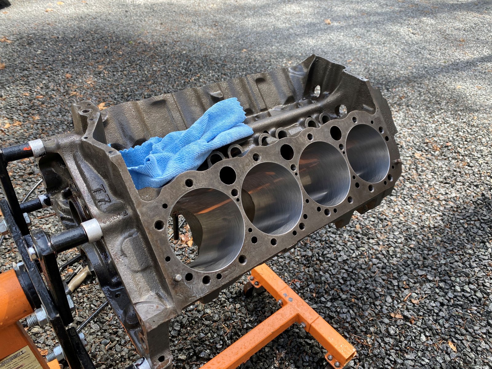
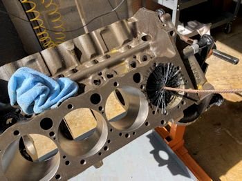
Then figured I would take out the cam bearings to get all the
nooks and cranies. |
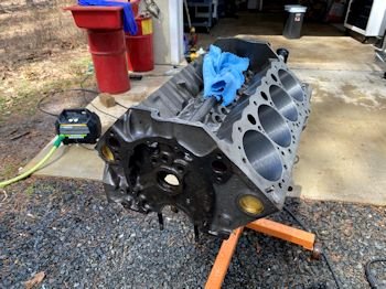
Hot pressure wash
|
Oil soaking with more WD40 |
|
 |
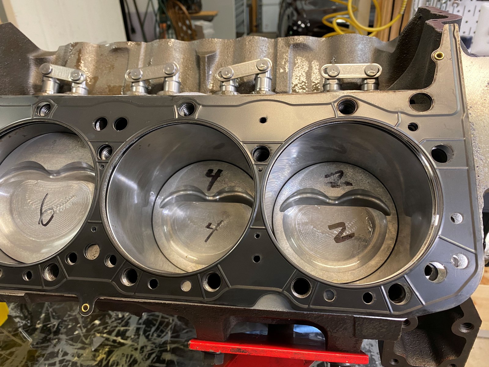
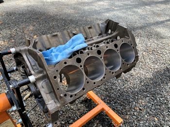
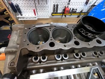
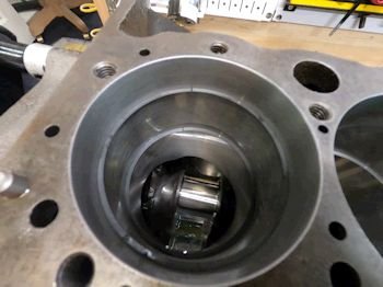
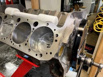
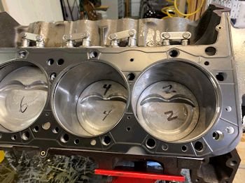
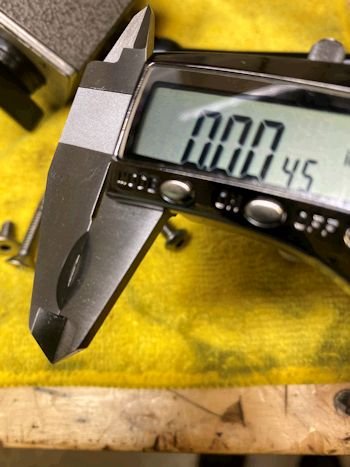
I put one piston in to verify that it's the right size and I
also measured piston to bore to be .004"
|
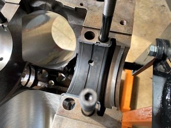
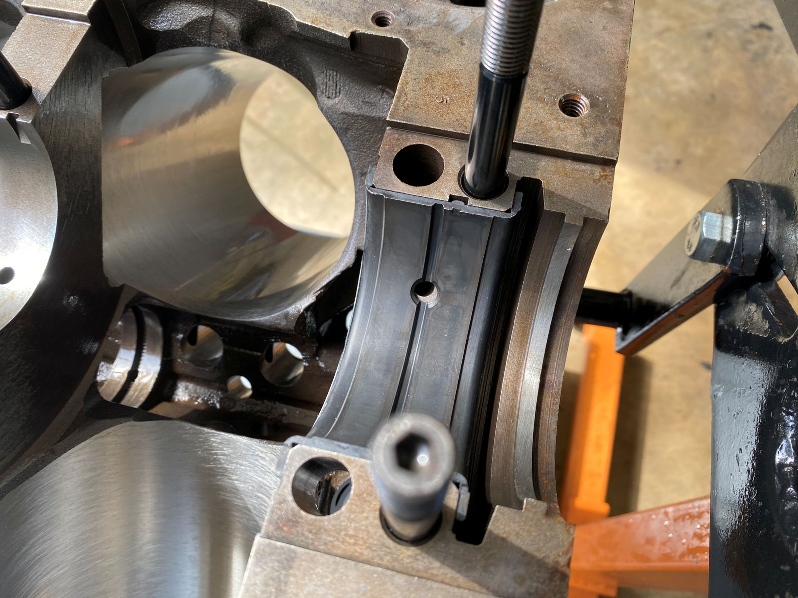
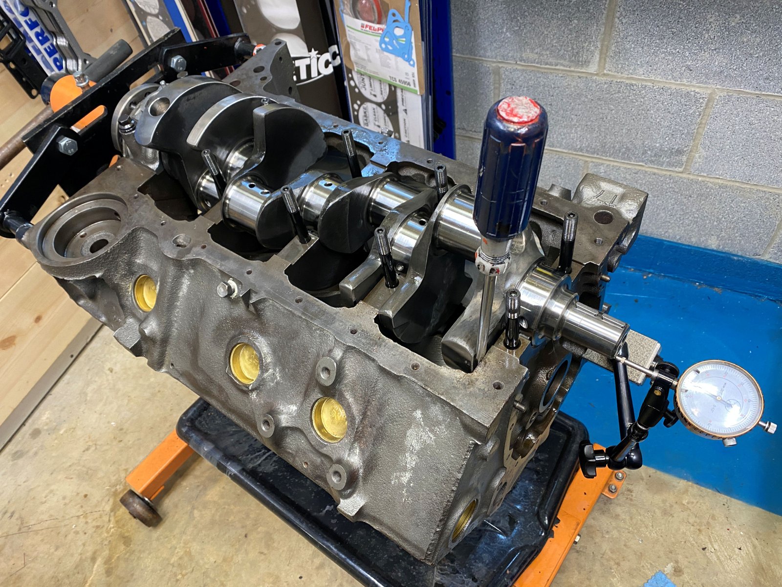
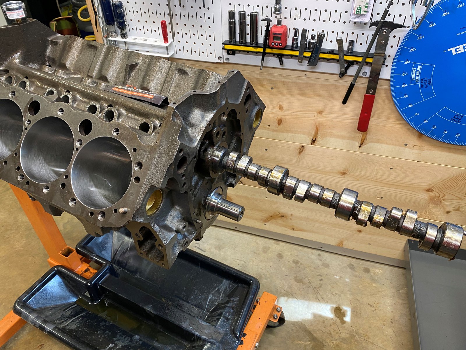
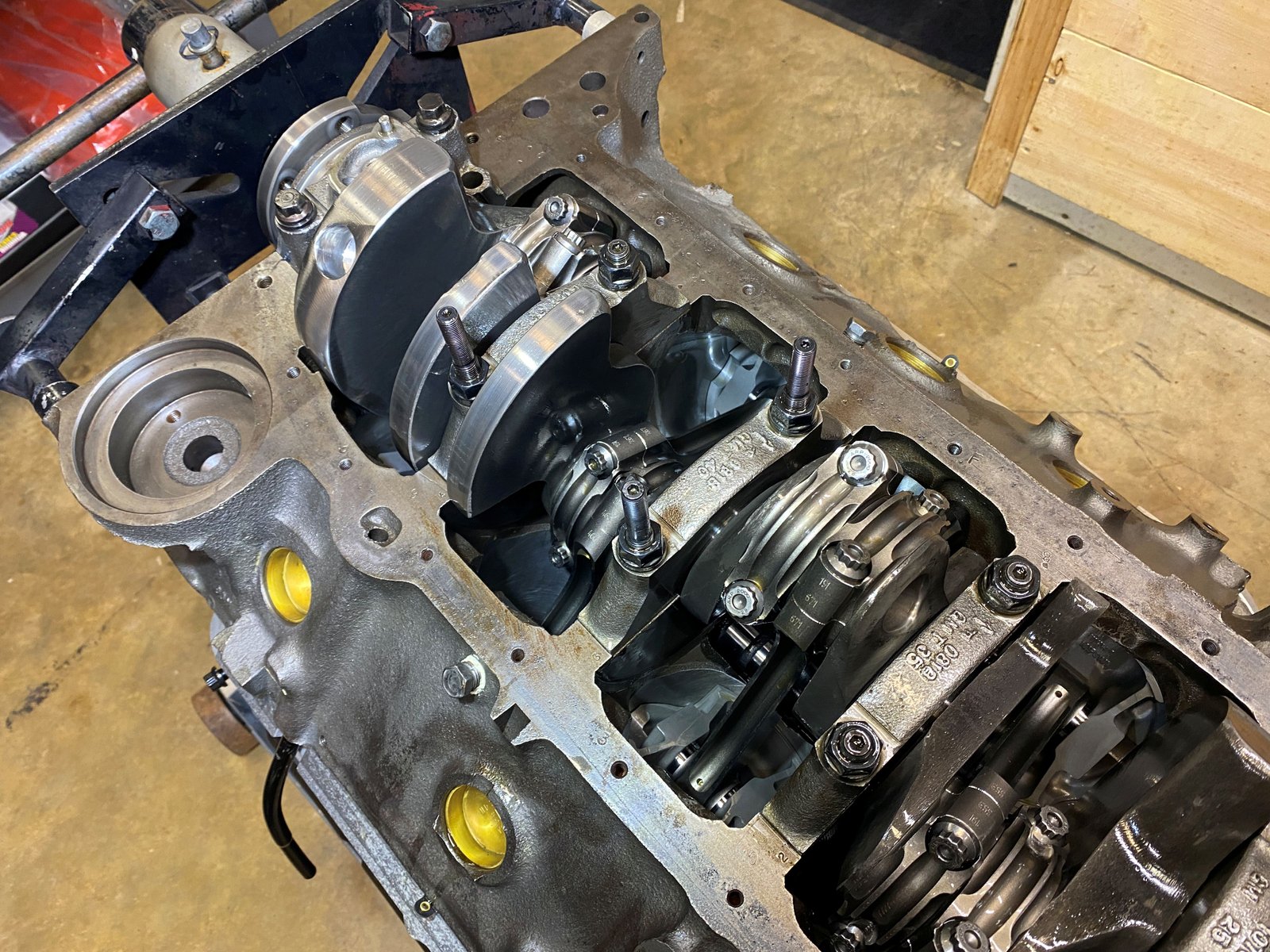
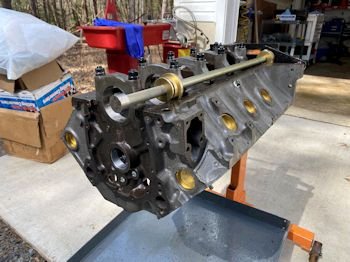
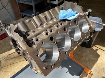
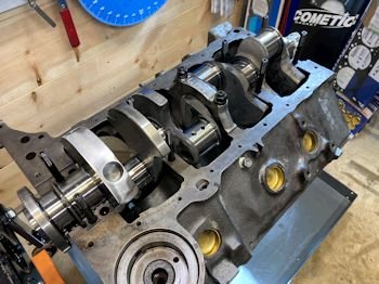
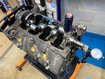
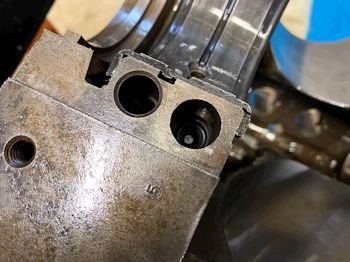
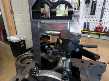
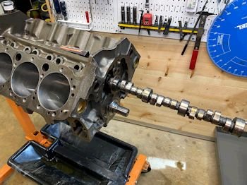
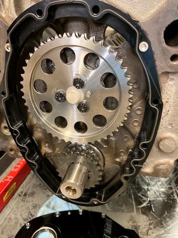
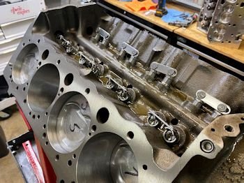
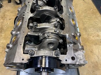
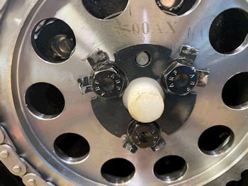
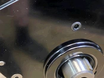
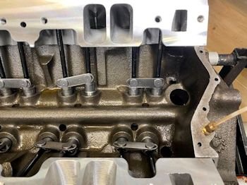
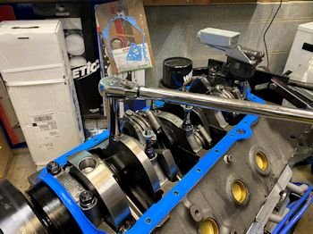
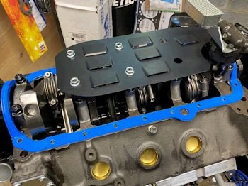
Prior to installing the cam bearings I'm going to mock up the
rotating assembly. The main bearings are installed
temporarily so that I can install the crank. This King
bearing will need to have the oil hole widened. |
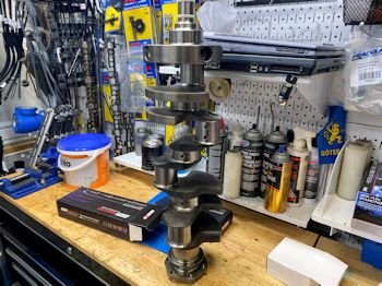
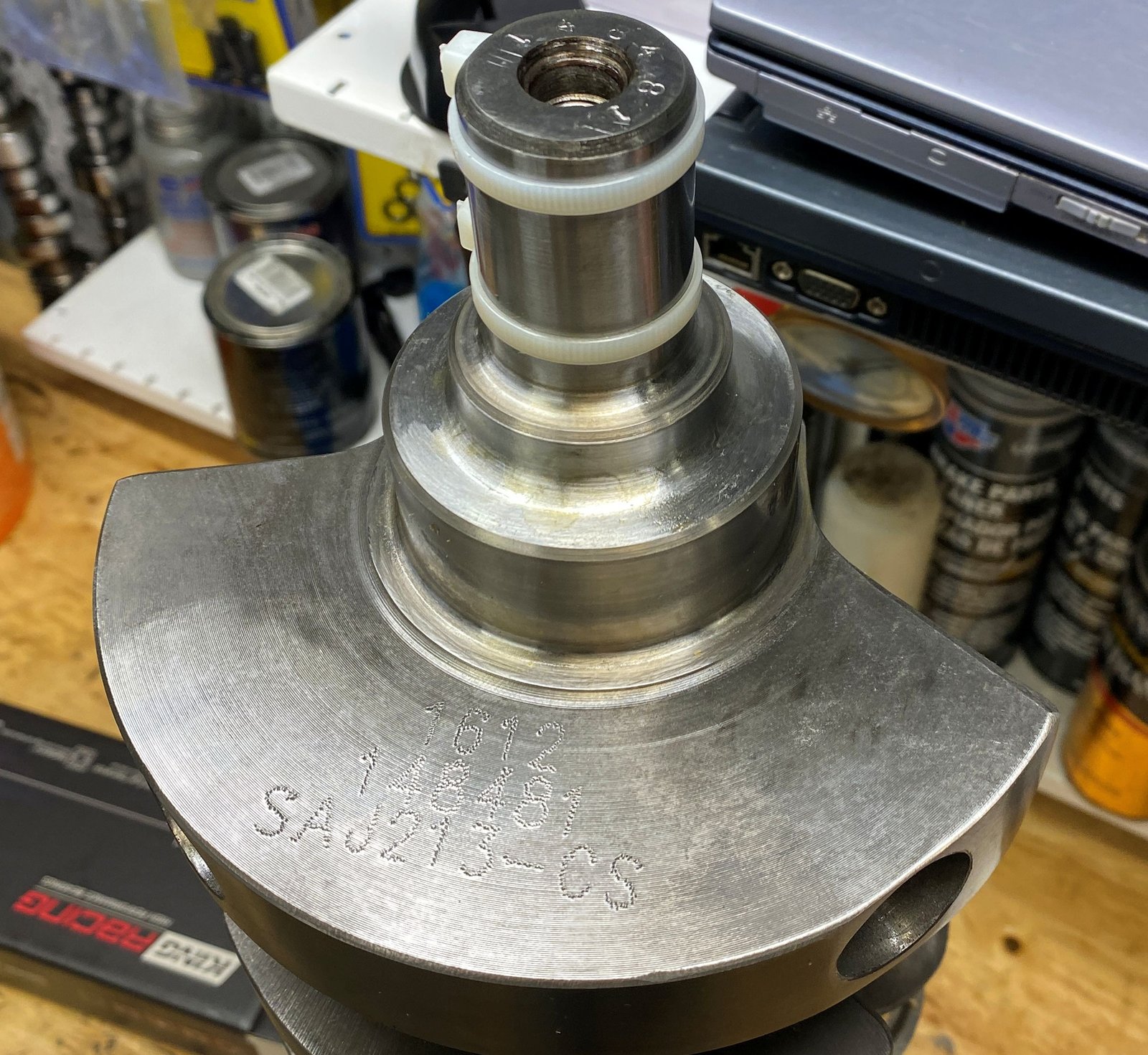
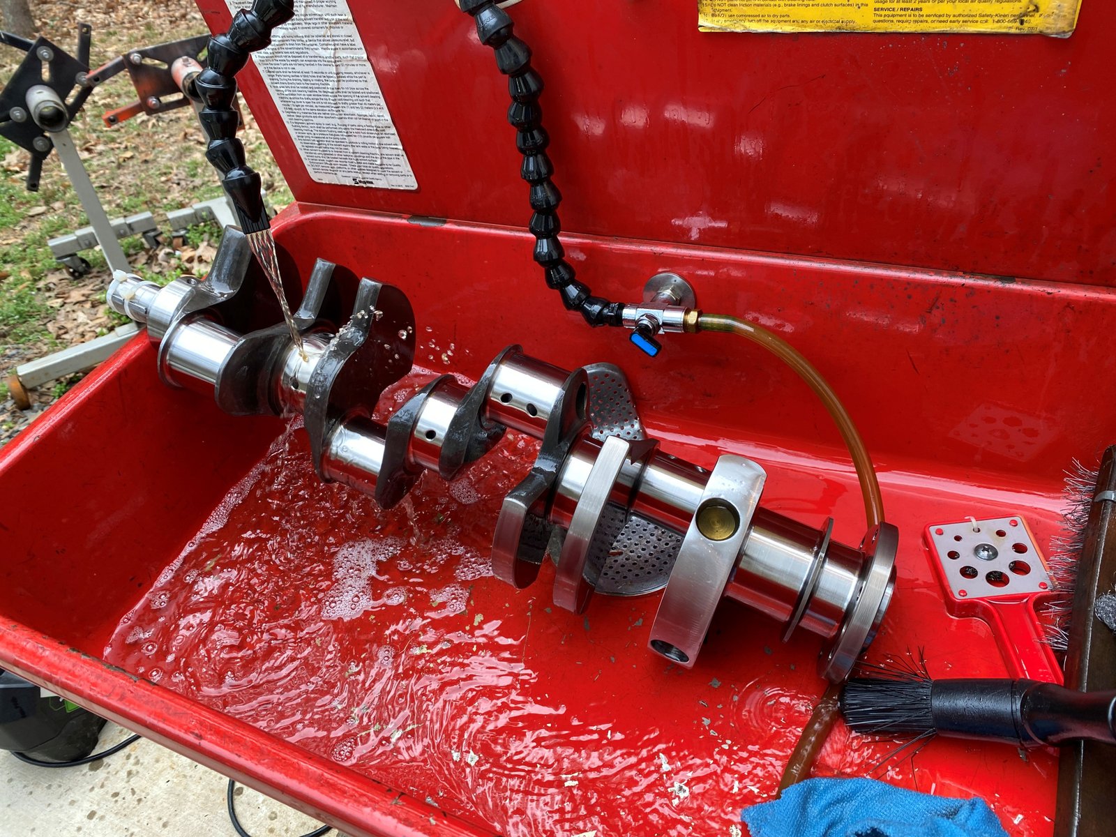
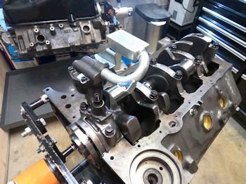
The crankshaft is from Callies. This is a full Compstar
kit. Mahle pistons, Compstar crank, Compstar H-beam rods,
Fully balanced by Callies, King main and rod bearings.
|
 |
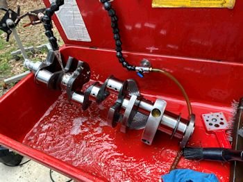
Washing the preservative off of the Callies crank.
|
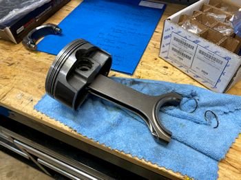
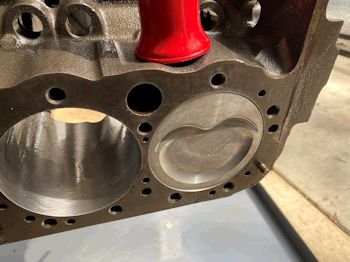
One rod/piston combo for mock up. |
The rod/piston placed in #1 hole showed good block
clearance...the photo did not "take".
|
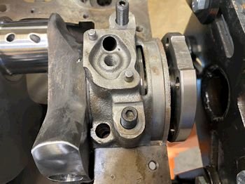
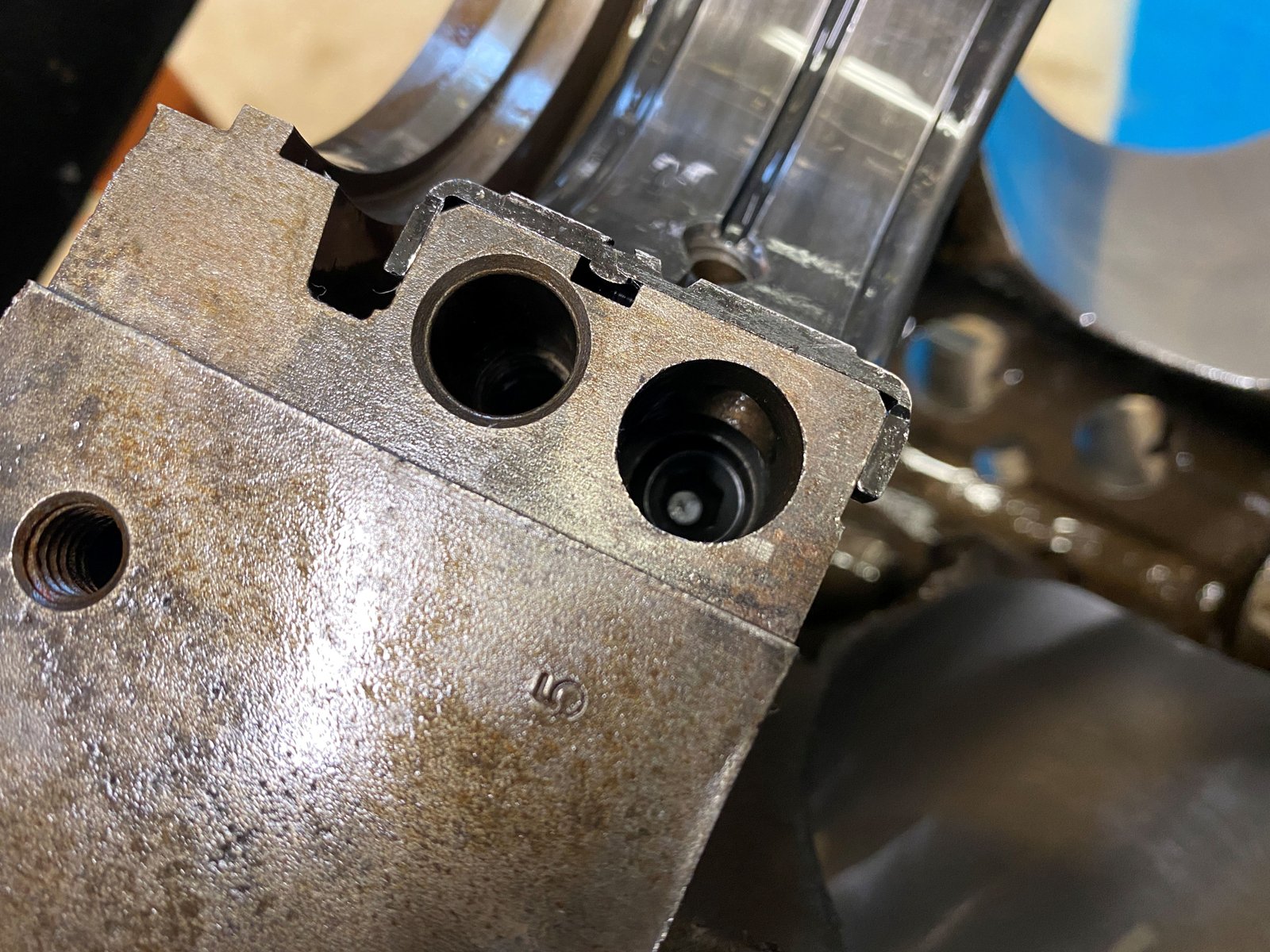
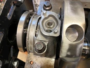
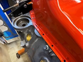
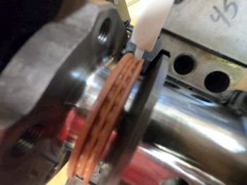
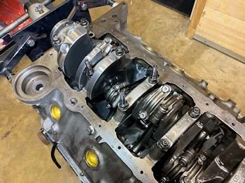
Now just a minor delay. The rear main cap gets bound up
a bit by the ARP stud. This causes the crank thrust to be
0.000" Without the cap on the thrust is
.005" I'll have Uncle Randy machine the bolt hole a bit
wider. |
The cap is still prevented from moving
into position because of the main stud. I guess I had Uncle
Randy machine the wrong side of the hole. Well the cap needs
to be able to move forward and it cannot. (see to the right)
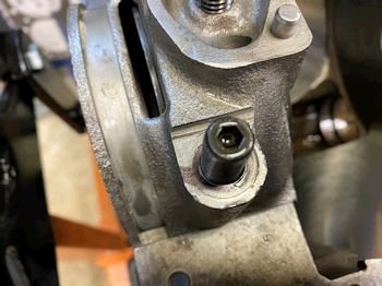
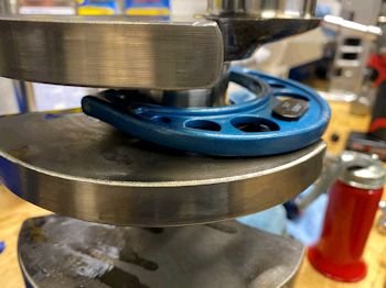
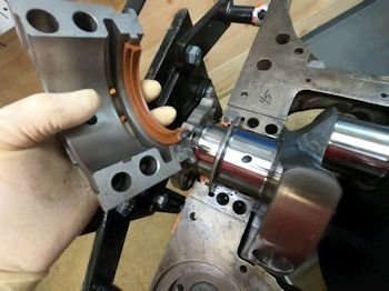
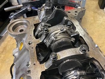
But with ARP main bolts the cap can
move into position and the top and bottom bearing thrust surfaces
can align. (see below).
Now the thrust is .006" after
all is said and done.
|
 |
|
Thrust is .006 with rear main torqued to 77 ft-lb |
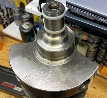
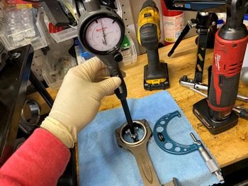
From memory the mains are 2.6484". This is obviously
the 400 SBC size. This is larger than the LT1 small block
Chevy.
|
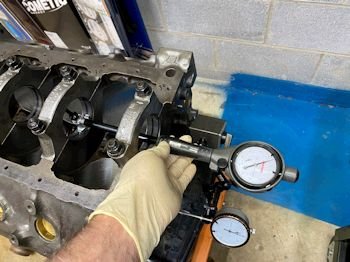
All mains measured .0030" except the rear main is
.0040" |
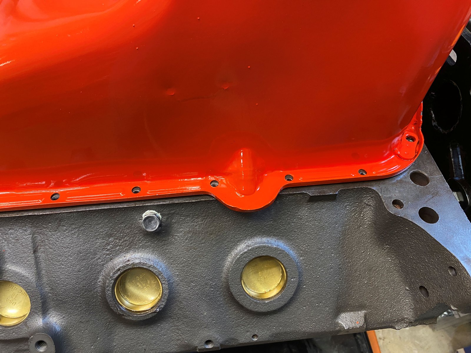
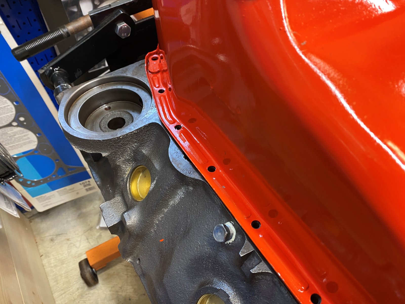
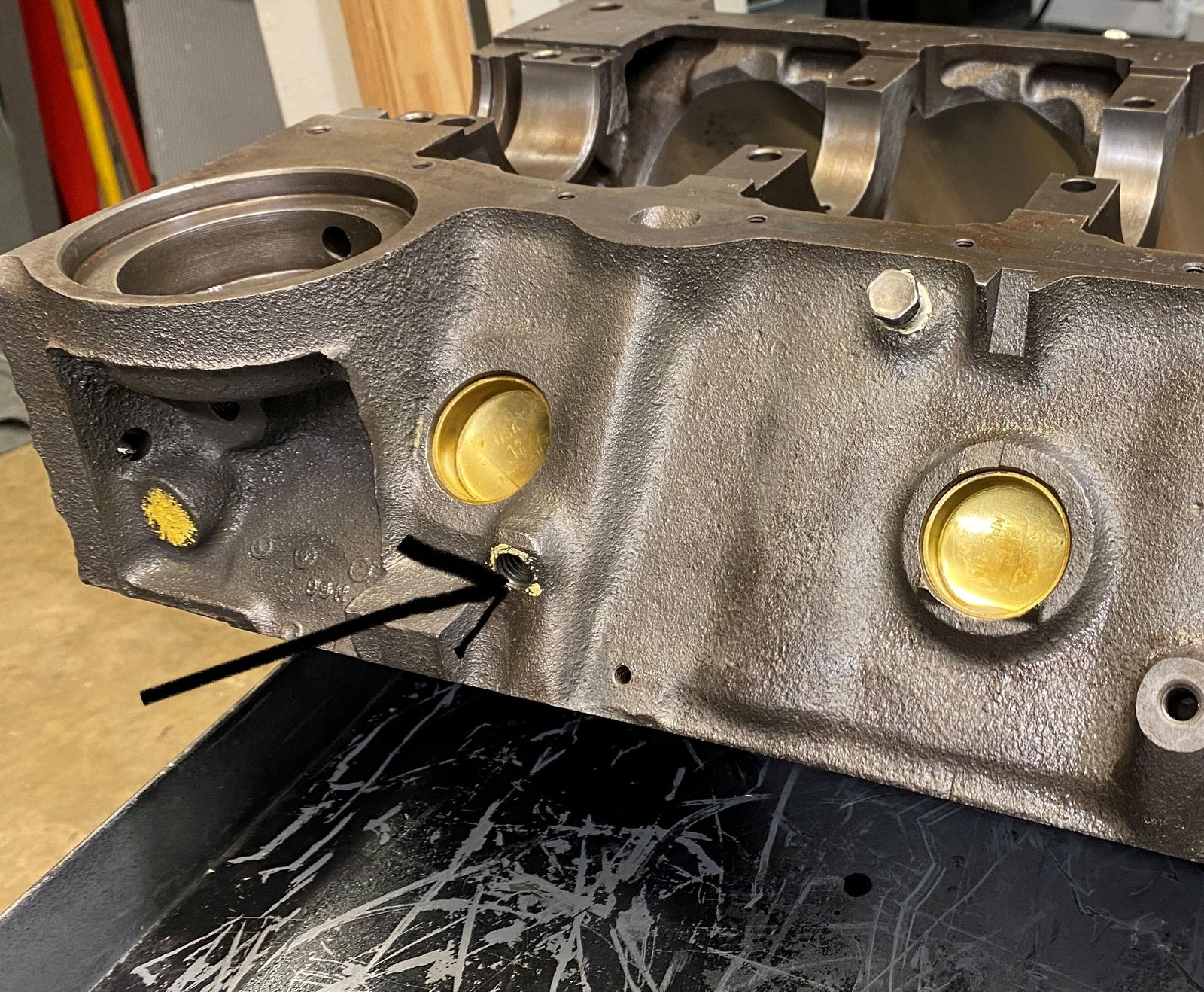
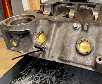
Oil galley plug.
|
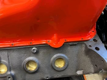
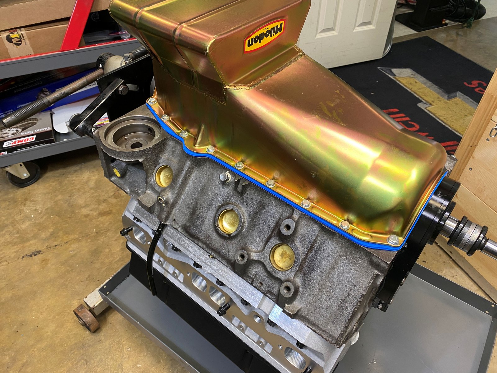
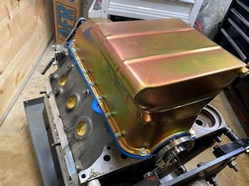
Now waiting on a new oil pan. This one has the dip stick
provision on the passenger side. It needs to be on the
driver's side. |
|
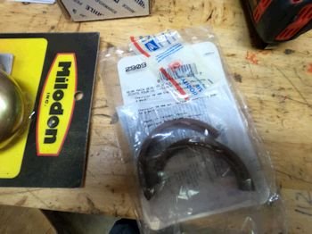
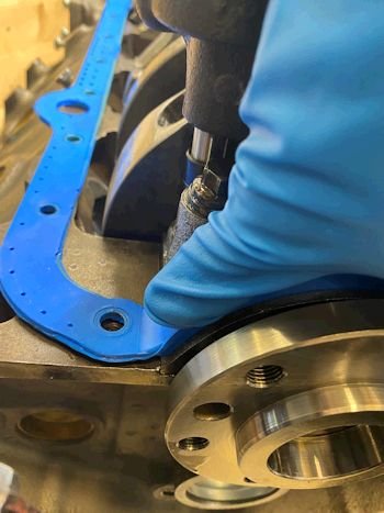
Now installing the proper rear main seal #2909. This one was
supplied by the customer and is for the 2.841" seal bore
diameter. I measured 2.836 at the seal bore and that is
pretty close. This feels tighter than the seal I had in
there and gives me confidence that it will seal. |
Blurry photo: I followed the directions and used this supplied
"shoe-horn" to keep the seal from nicking.
|
3/8" offset and a dab of RTV just like the directions show.
Then I torqued the main cap and re-checked the crank thrust is
still at .005".
Yes I did put the other bearing 1/2 shell in there prior to
installing. :) |
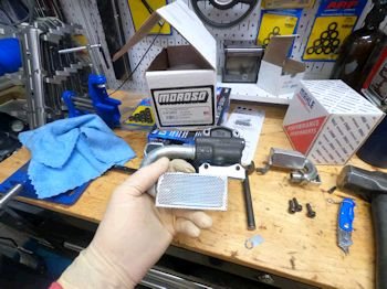
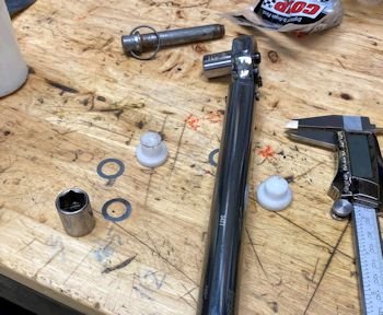
Here is the 8.25" oil pump pickup I ordered.
|
Measures 7.75" off the block. The oil pan is 8.25" deep
and so factor in the oil pan gasket so that gives between
3/8" and 1/2" pickup clearance. |
|
The oil pump is a Melling shark tooth 10554ST with the
3/4" inlet and the pick up is Melling 24360 for 3/4" oil
pump inlet. |
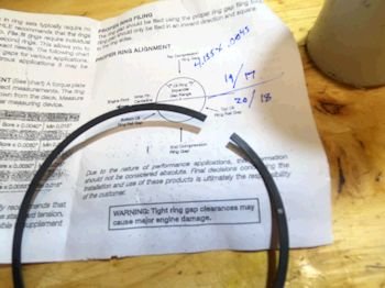
Ring gap calculated for performance street. I am shooting for
.020" top and .018" 2nd ring.
|
Over shot just a bit and I'm at .021" top and .018" 2nd
ring. |
|
Rod bearing clearance at .0022" using King CR807XPN |
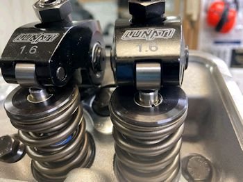
Cam design by Dennis Staff. This is from Erson
230/234/106ICL, .584"/.584" lift with 1.6 rockers.
|
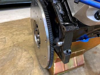
Block went to Bill Koustenis (Advanced Automotive Machine in
Waldorf Maryland). He cleaned up the deck in order to allow
me to install MLS head gaskets. He also drilled and tapped
that hole for a clutch pivot. |
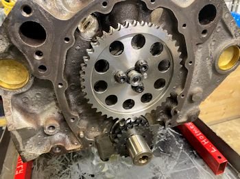
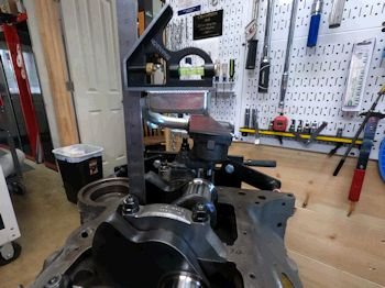
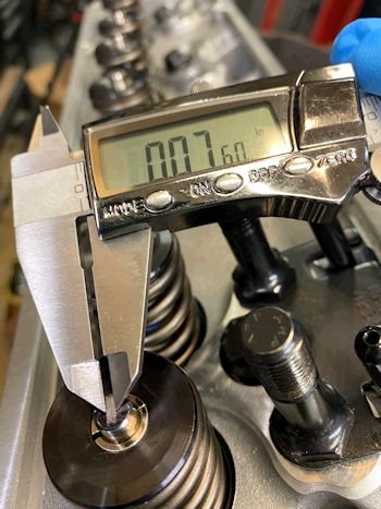
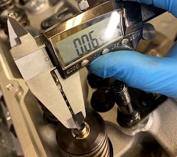
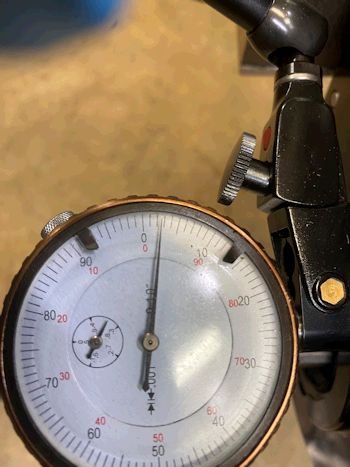
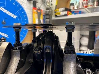
Here is a first attempt at getting proper cam end play.
Spec is .001" to .005".
|
Not shown in the photo but I gave up on the thrust bearing. |
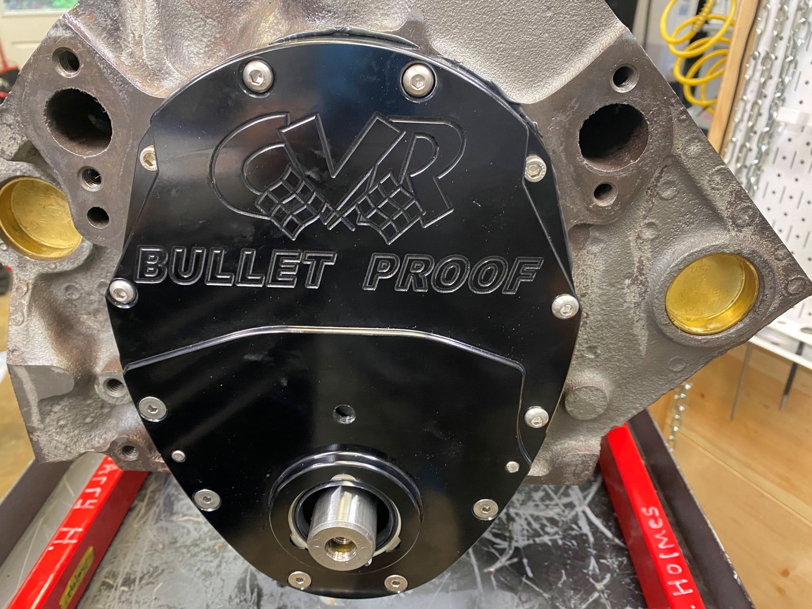
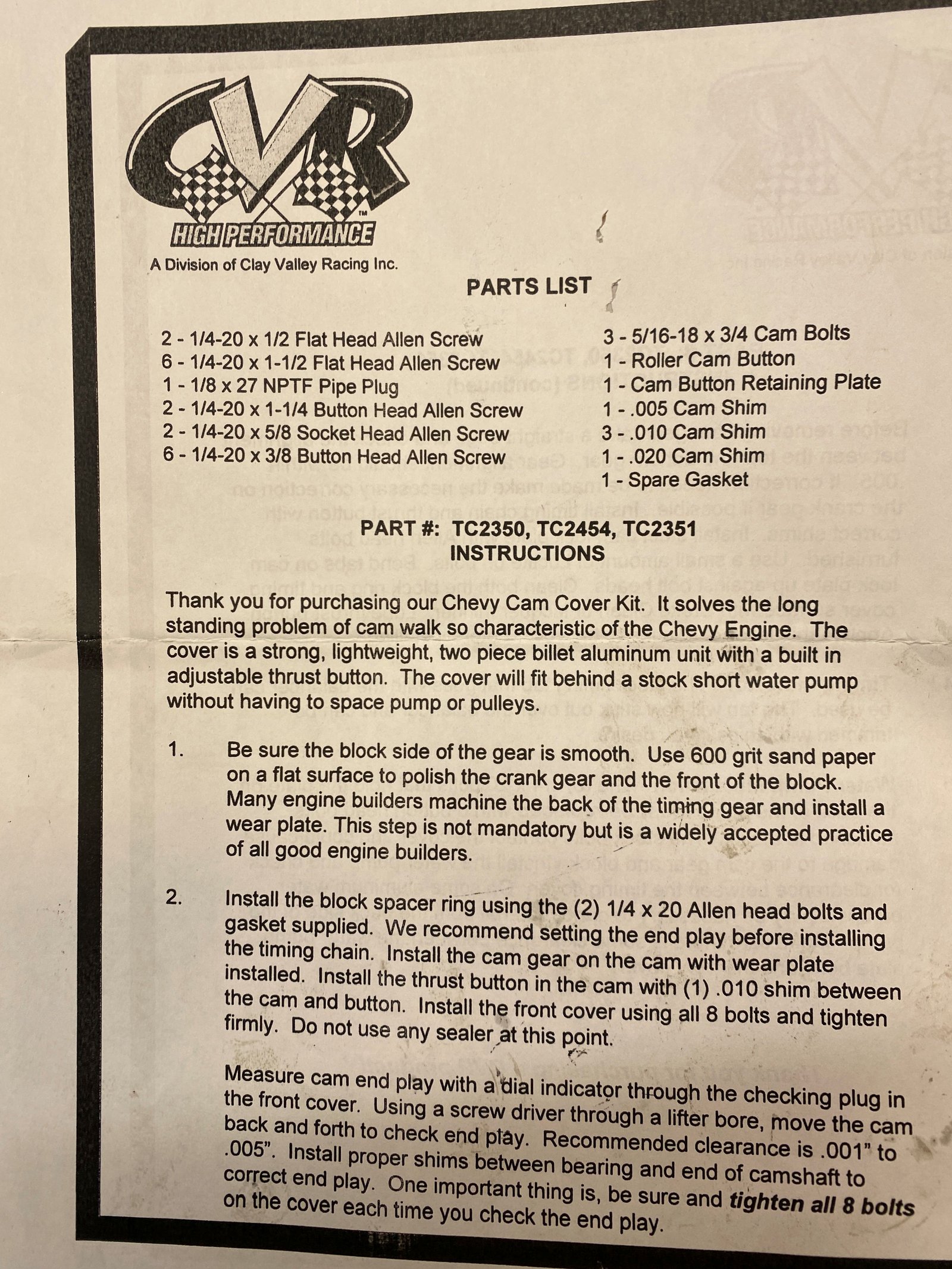
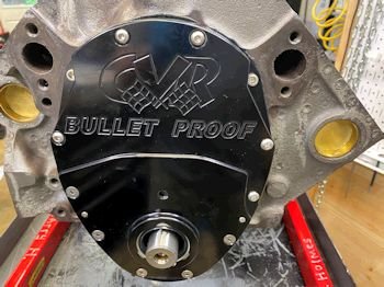
This is the part number for the nice 2-piece timing cover.
|
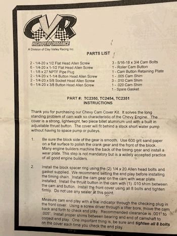
Instructions for cam end play. |
|
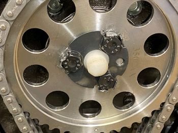
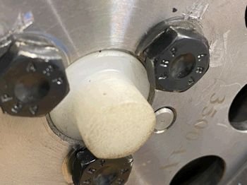
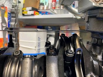
In the end we went with a
nylon button. |
More about the cam button: I trimmed too far again (by
about .005") and so I put a .005" shim behind the
button. It actually worked. Right now the cam end play
is .001". It changed later to zero (after changing the
crank sprocket position to +2*) but I'll tackle that later.
|
So here we are after spending 2 days getting cam end play
right I certainly want to degree the cam shaft again after having
the chain off. In the end the +2* position is the closest to
perfect.. |
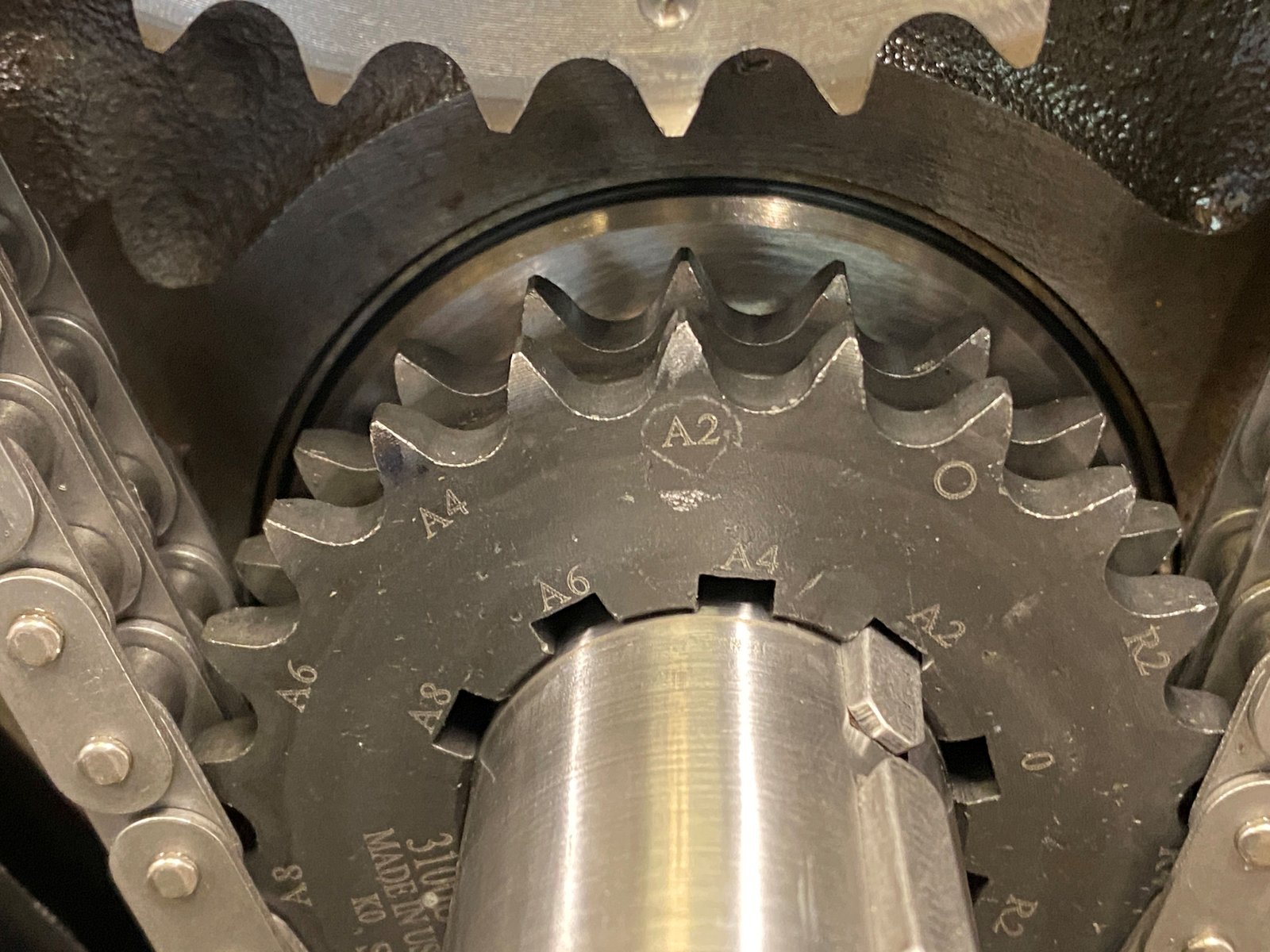
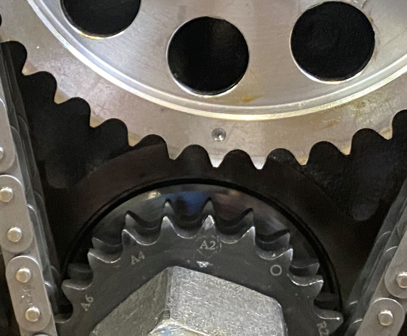
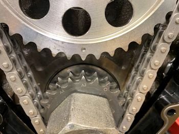
Perfect being 106 deg intake centerline. The A2 crank
sprocket position gave 105 deg intake centerline (actually 1 deg
advanced).
|
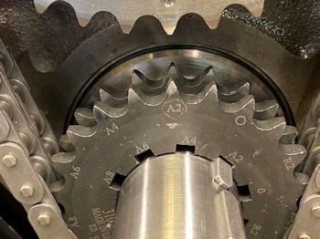
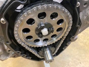
I etched a circle around the A2 spot for future reference. |
I've had the bolt locking plate on and off a few times you can
see.
|
I thought better of using that plate. I took it off and
now am relying on blue Loctite on the bolts and 20ft-lb |
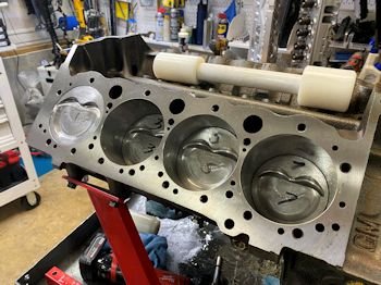
All pistons in.
|
 |
|

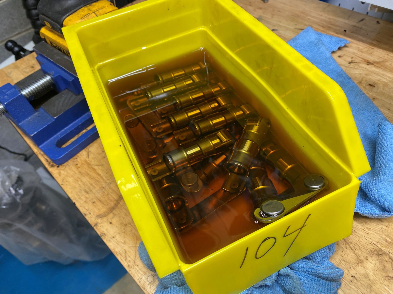
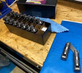
Hydraulic lifters blown off with air and soaking in oil. |
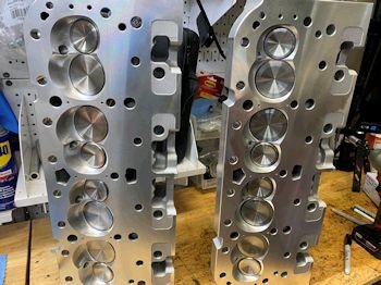
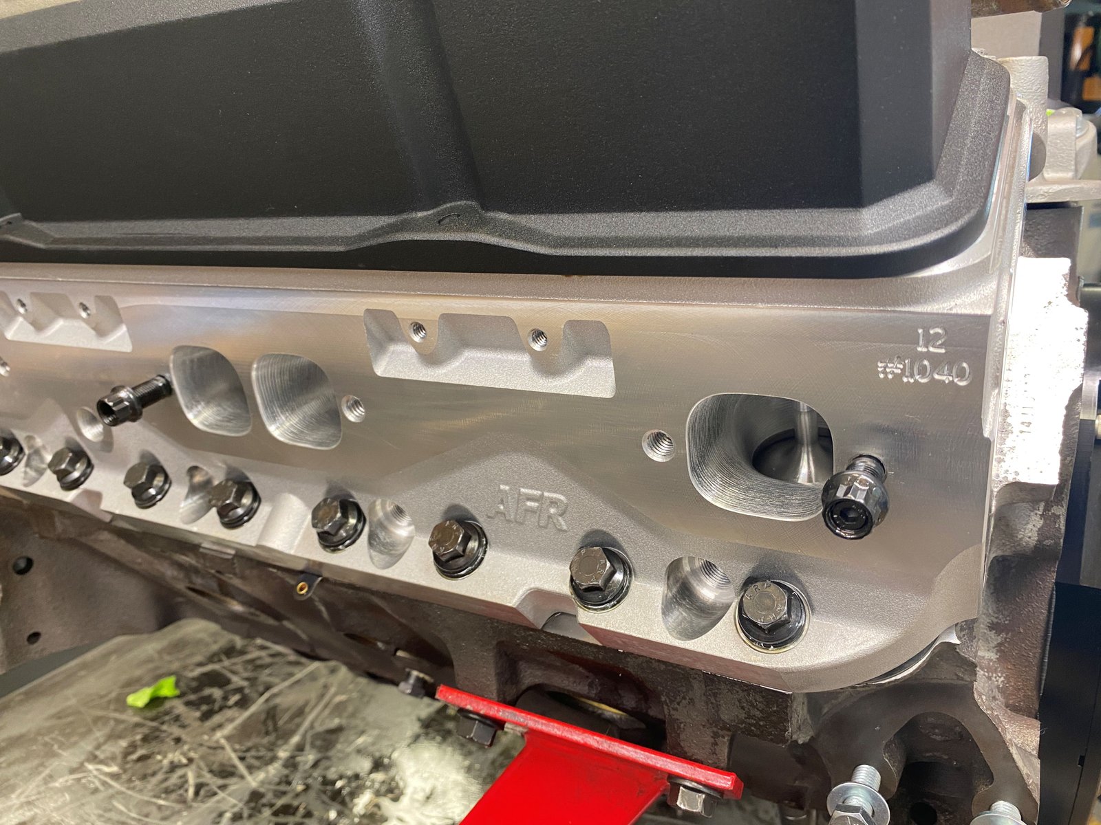
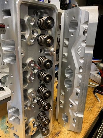
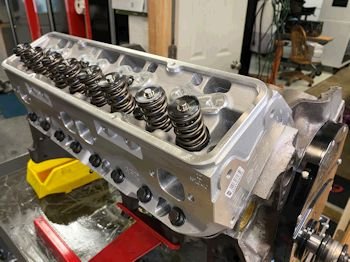
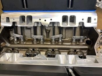
AFR heads
|
 |
|
Cometic MLS gasket (.027" thick) |
|
 |
Rocker geometry with 7.200" pushrods.
|
 |
|
This is the rocker tip sweep with 7.250" pushrods.
I'm happy with this slightly narrower sweep compared to the
7.200" pushrod. I don't want to go to a 7.300 pushrod
and have the rocker too far on the outer edge of the valve
tip. |
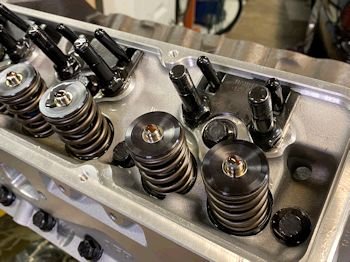
Grease on the valve tip and oil on the pushrod.
|
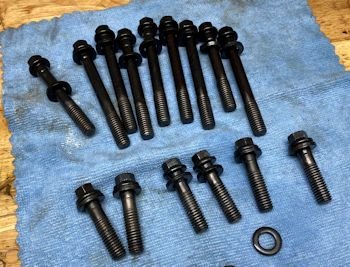
Used ARP head bolts all cleaned up. Up until this point
I only had the passenger side head on. |
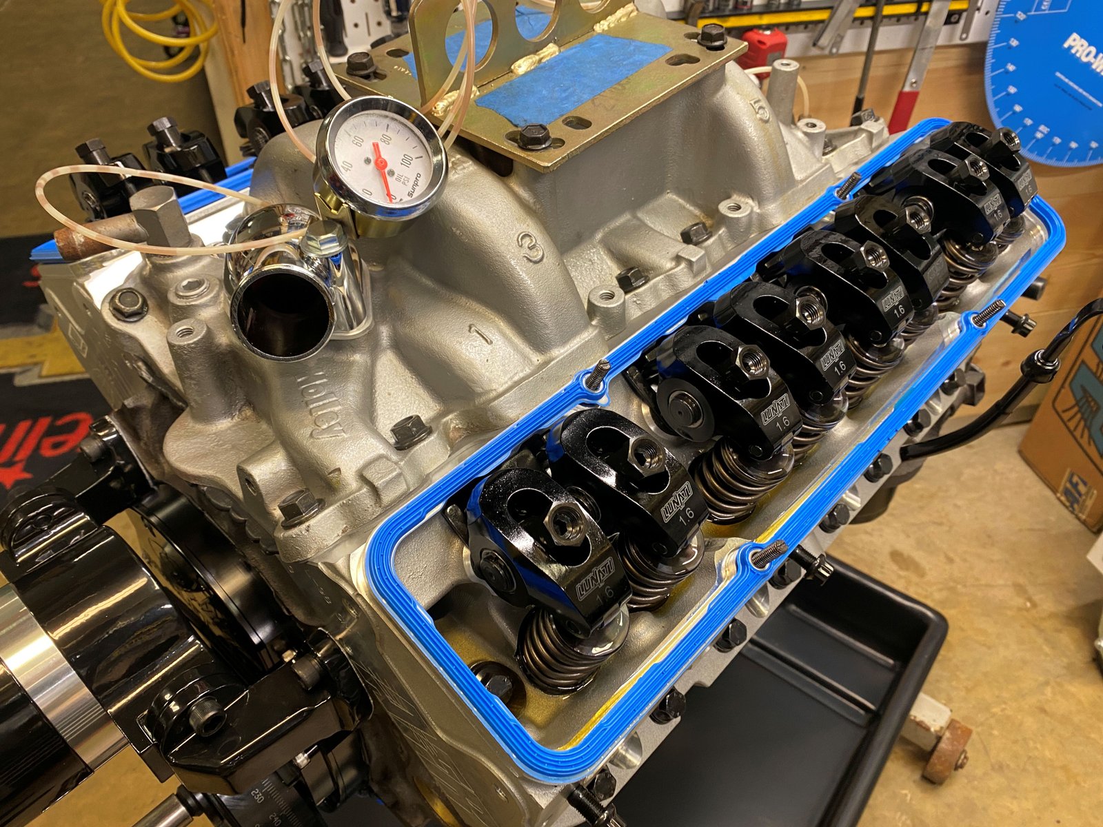
Now both heads on and all rockers on.
|
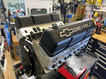
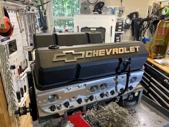
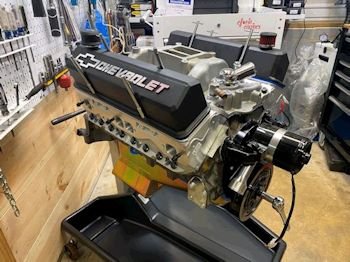
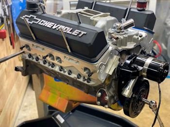
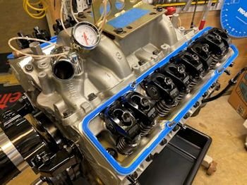
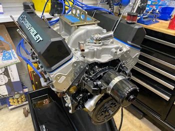
I really like the valve covers. They are on temporary
for dust intrusion prevention. |
Intake manifold on without gasket to check for fit. It
looks good.
|

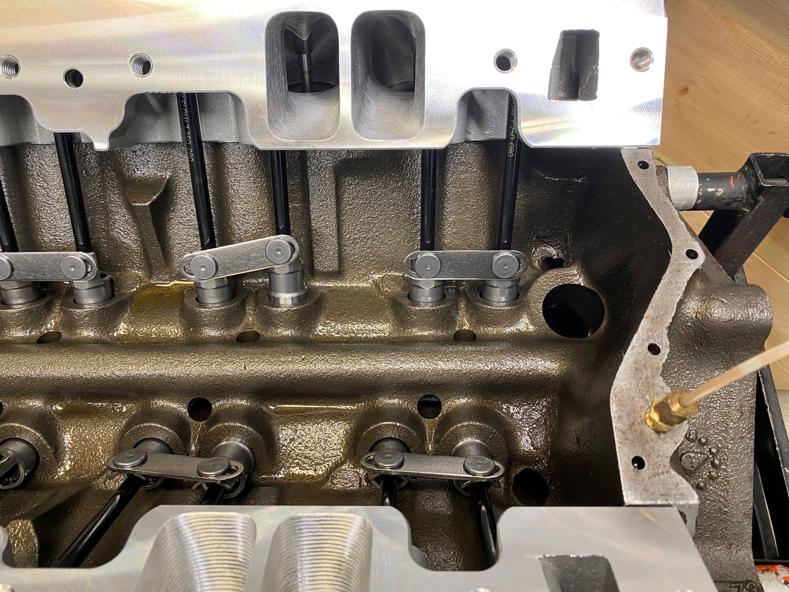
Just a nice view of the AFR heads. |
Buttoning up the bottom end. Rods are torqued to 75ft-lb
and rod side clearance is .018"
|
Notice the windage tray studs. |
Now they are swapped out with regular sized studs. The dip
stick is on the opposite side for my windage tray that I was going
to install. So the oil pan will have to deal with windage.
|
 |
|

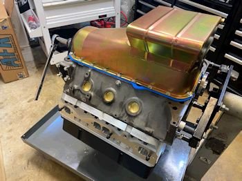
Oil pan gasket and oil pan look like a good fit, *by eyeball*. |
|
 |
|
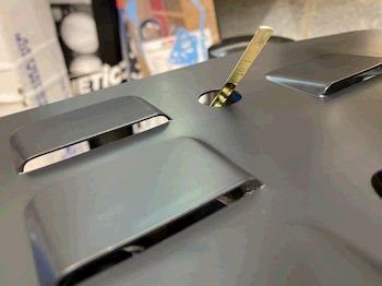
<----To the left is the
.005" shim that I put behind this cam button.
 |
|
A bit of a story here: I
attempted to verify the cam end play with the timing chain
on. The cam would not move. I believe that the chain
tension prevents that. And so that must be why the
instructions say "measure cam thrust with the timing chain
off". And so I took the chain off and verified cam end
play for the last time. The final result is .0025" to
.003"
Then prior to final installation of the cam sprocket I
squeezed a little bit of grease on the thrust plate and also made
sure the cam seating surface was clean. |
Here the cam nose was wiped clean and verified clean prior to
final assembly. There was some dried up Loktite on it.
|
The cam bolt retainer plate looks a dinged up but the metal is
good quality and soft. |

|
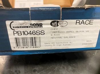
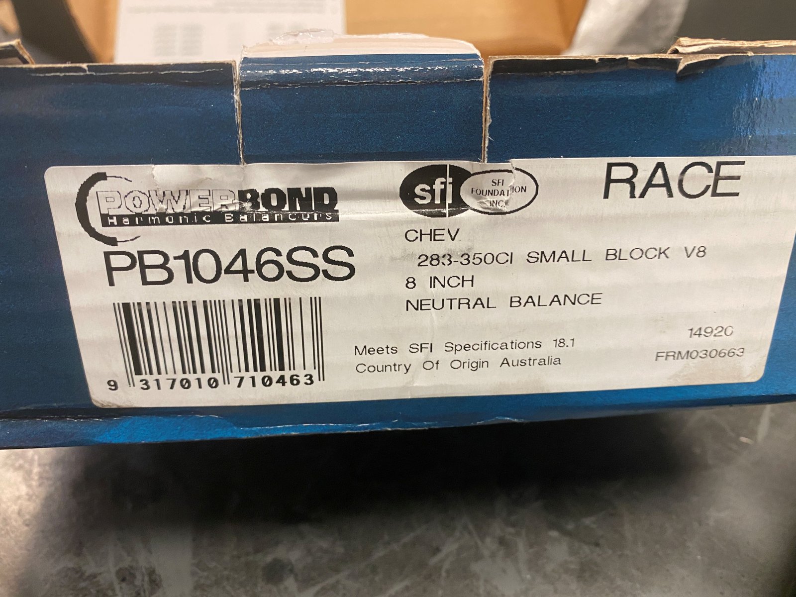
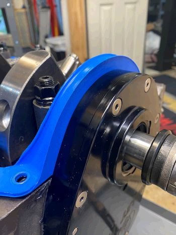
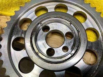
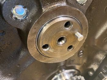
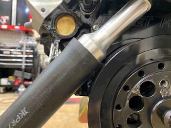
This is the Powerbond neutral balance damper. Good
quality. |
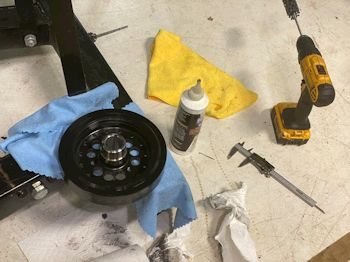
The instructions require a .001" interference and it was
003" (crank diameter 1.246" and hub inside diameter
1.243"). After a few moments of honing the hub is now
1.245".
|
I did not forget to install the cam thrust checking access
plug. |
Here it looks like I'm taking off the damper. I am taking
it back off (not all the way). Turns out the timing cover bolt
cannot be removed with the damper on. I need that bolt for the
timing pointer. The press/pull tool makes it easy.
|
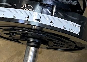
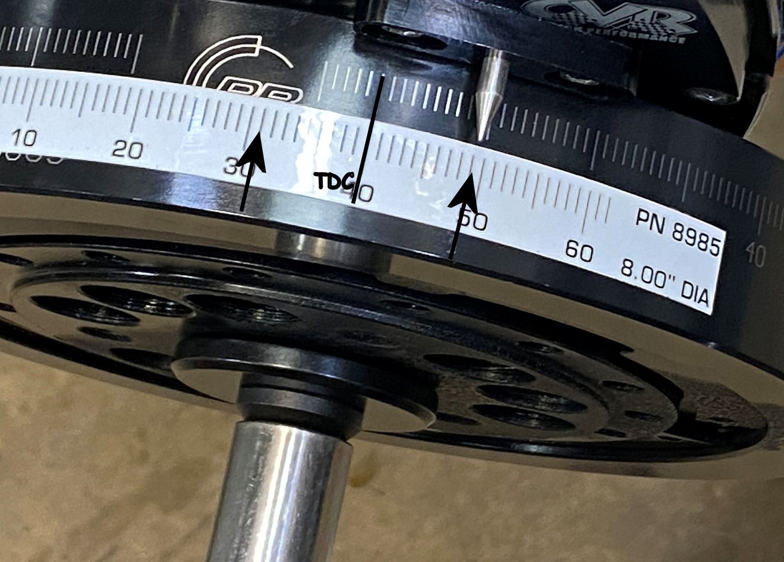
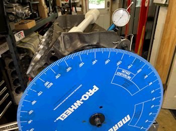
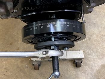
ARP crank bolt torqued to 90ft-lb and then TDC verified and
pointer adjusted. I put the tape on to help me see the left
side of TDC. No timing marks after 5* ATDC because that is where
the PB logo is. The pointer went to 9* BTDC and 9* ATDC with
my piston stop inserted at the spark plug hole for #1 piston. |
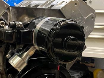
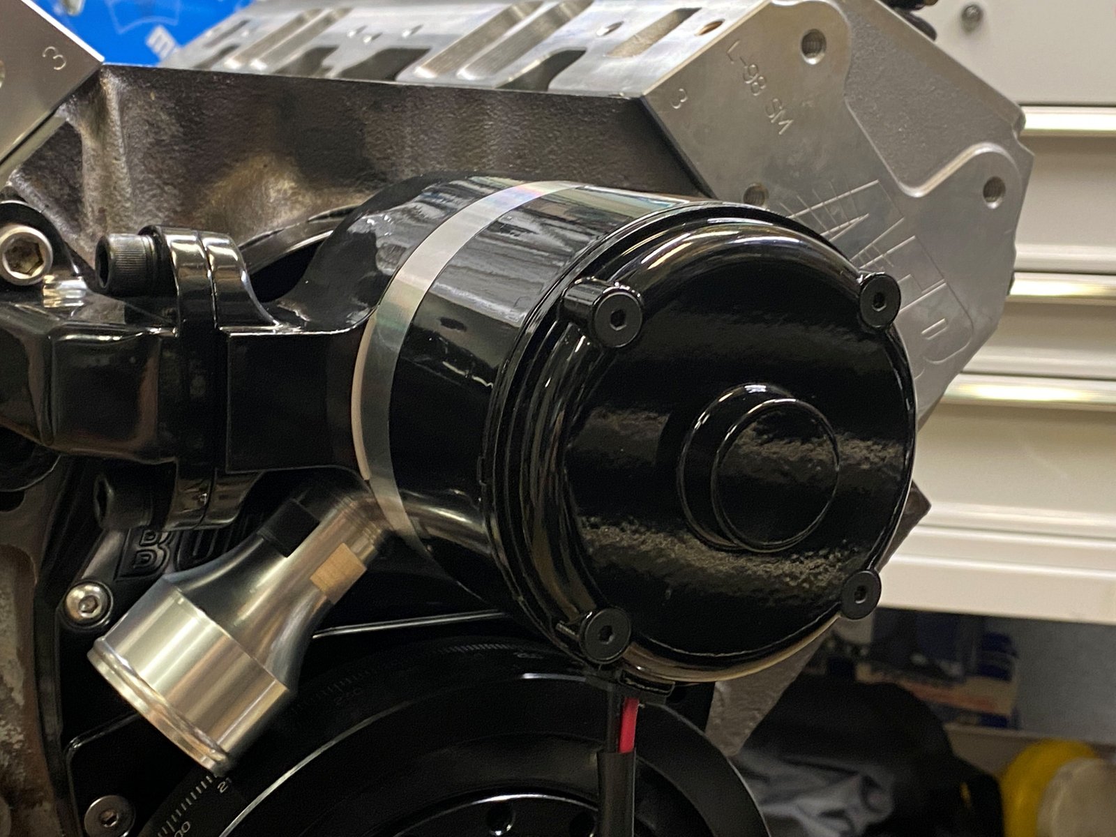
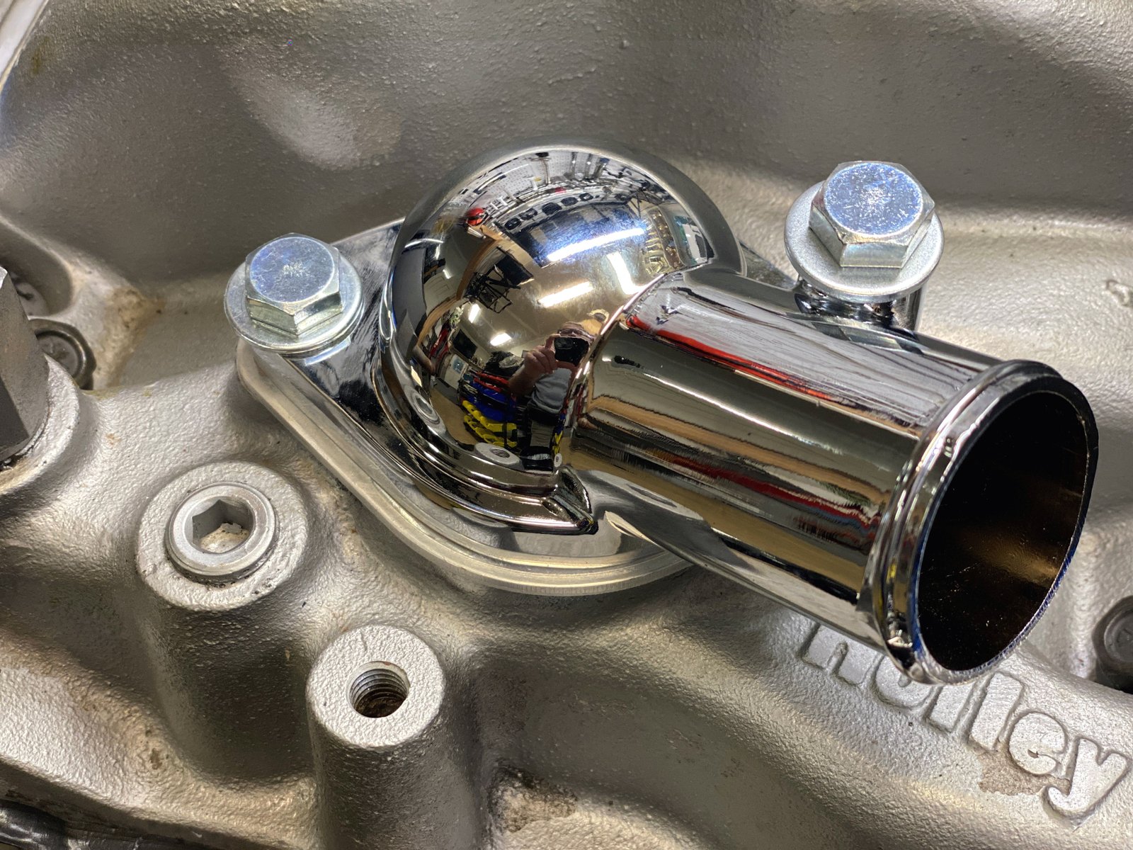
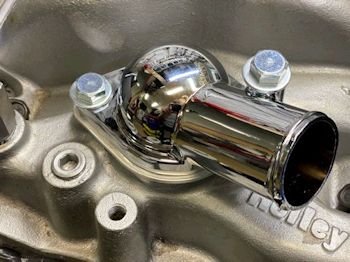
I have the Summit #316104 (5") lower radiator hose nozzle
on order. This one is too close to the 8" damper.
|
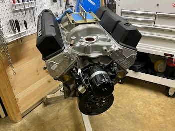
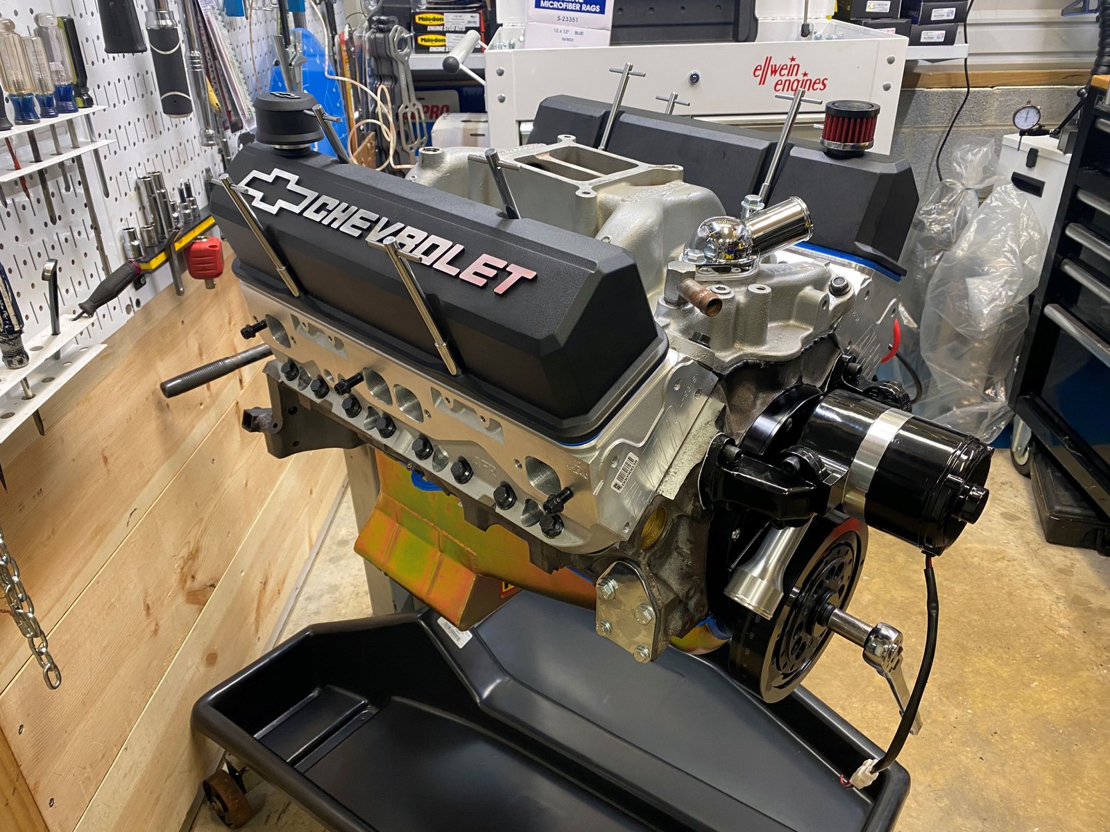
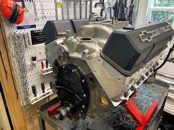
Darn near complete and ready for the dyno.
To Do:
1. Fuel pump block off plate
2. Water pump 5" nozzle
3. Oil pump spin with drill |
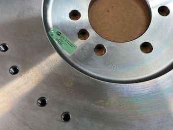
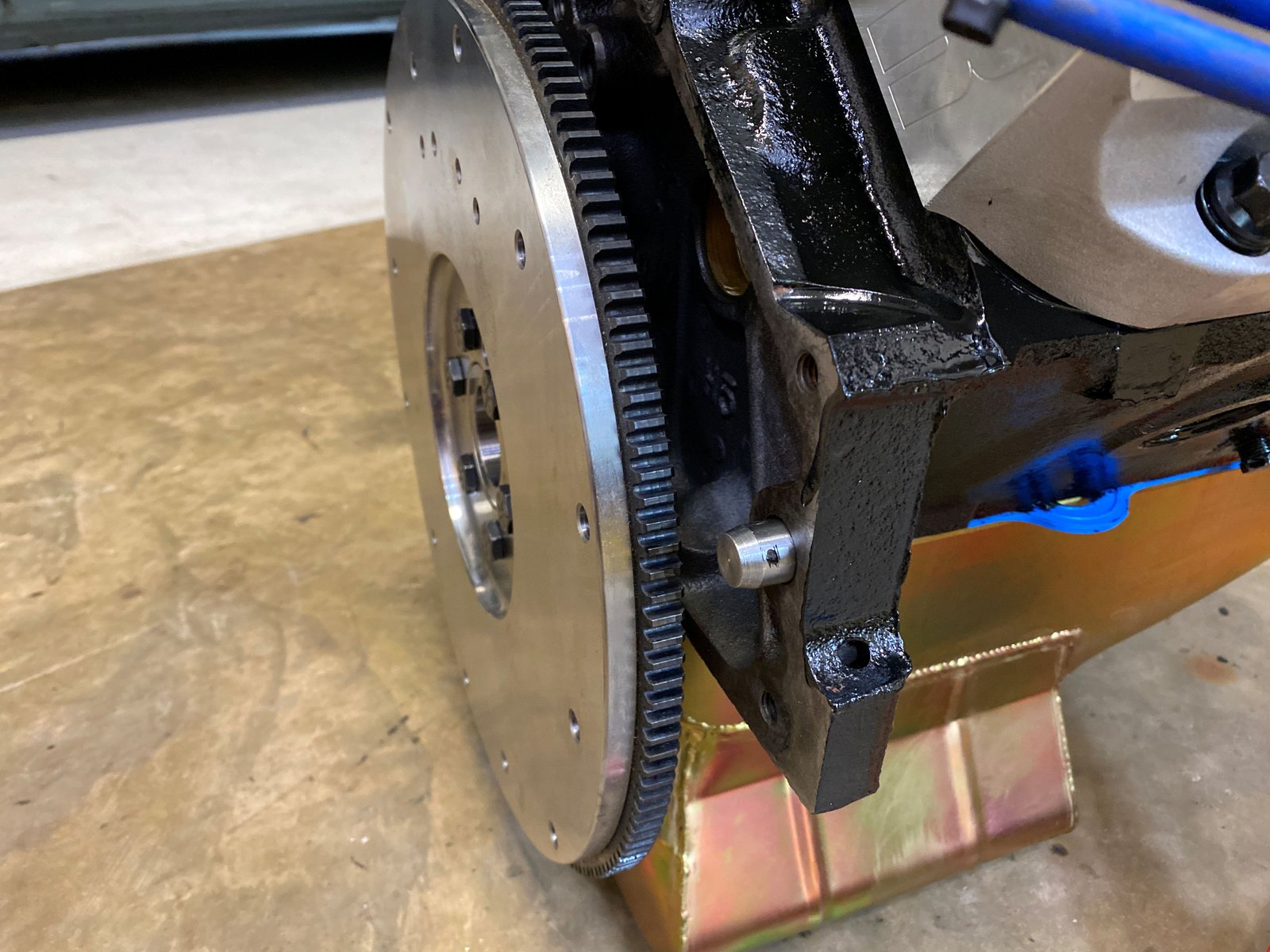
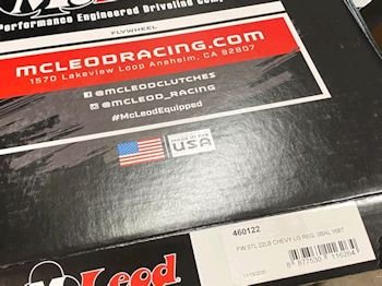
Photo of the flywheel for the SFI record.
|
 |
Last view of the heads before I put the intake manifold on.
|
 |
|
 |
|

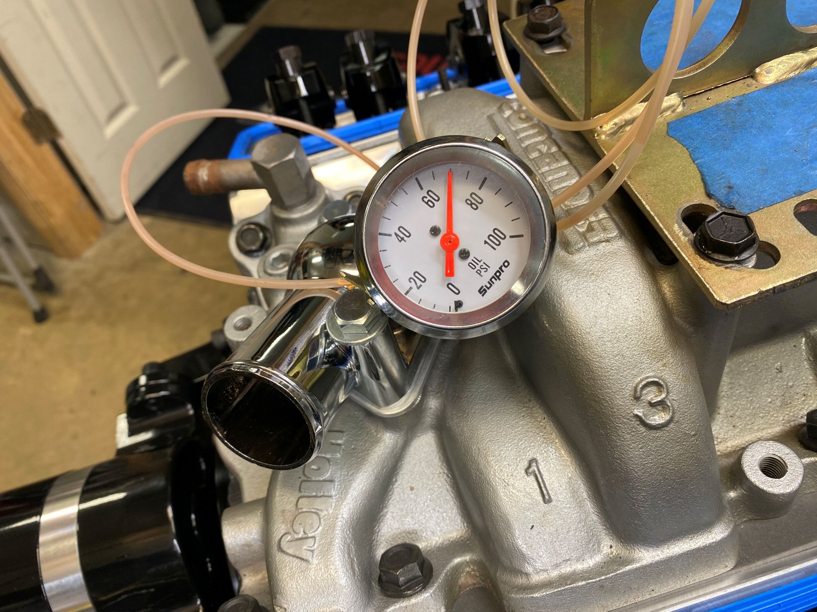
First spin of the drill shows 70 psig for oil pressure. |
The lifters sent oil up the pushrod and onto the rockers and
springs.
|

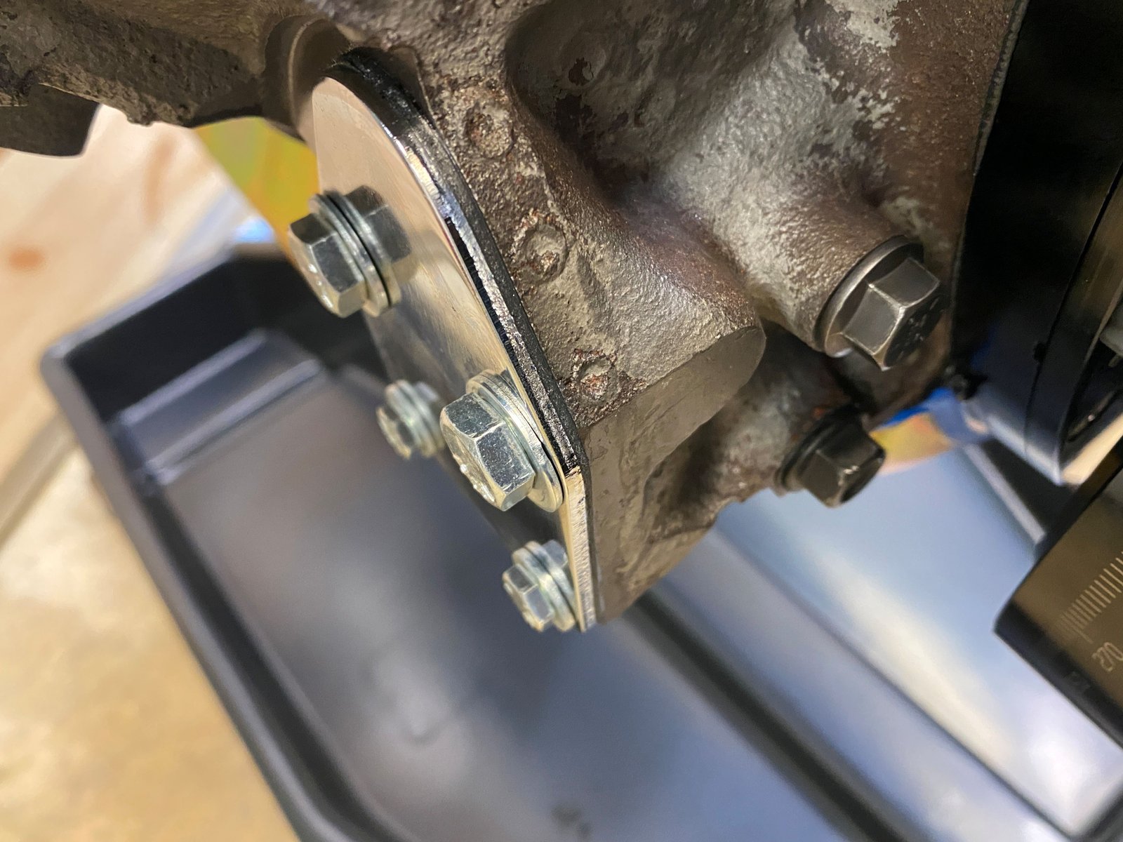
Smoke test of the crankcase (to look for leaks). Only
leak found was where the front two bolts are and at the fuel pump
block-off plate. RTV on the plate gasket and will check
again tomorrow. |
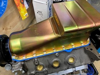
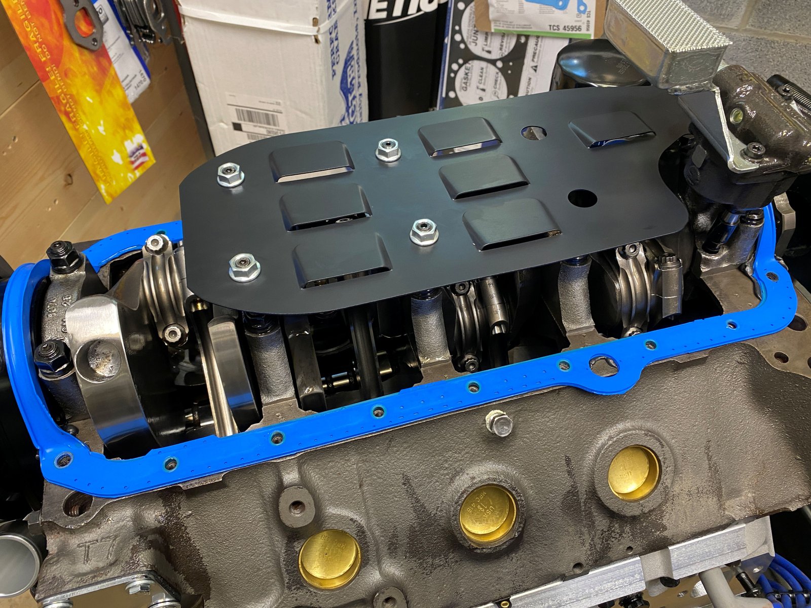
Windage tray time. I should have procured one earlier in
the build. It's not too late. The oil pan gasket is only
RTV'ed to the block corners. The pan came off nicely.
|
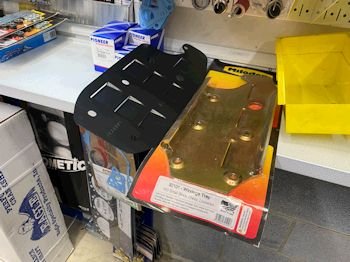
I'm choosing the black tray for it's oil shedding coating. |
Back to the windage tray studs. I do them one at a time
and make sure I don't forget to torque them.
|
 |
No bending of the tray needed. It fits well. The oil
pan fits over the tray without interference.
|
 |
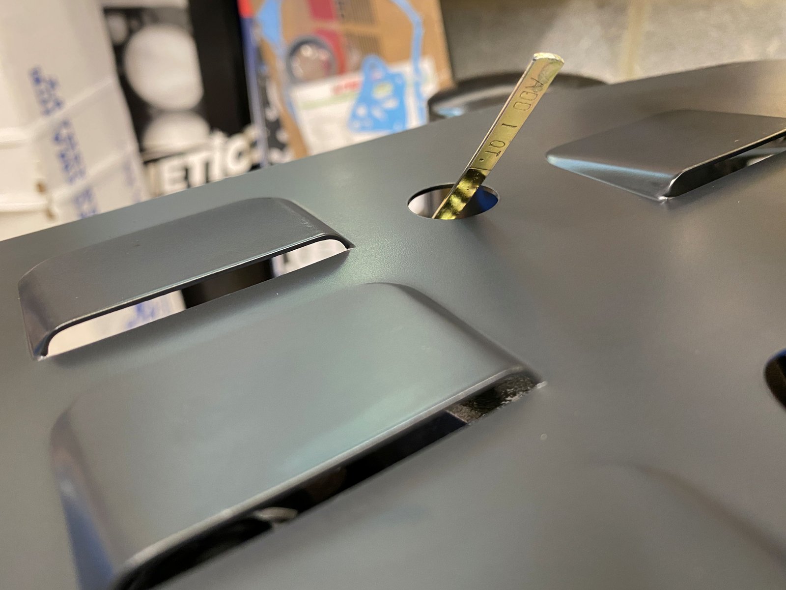
So it looks like if oil is just up to the bottom of the tray
then that is "full".
|
POR-15 Black engine paint. Ready for the engine dyno. |
This will probably work for the dyno but an even longer water
pump nozzle is needed for the future.
|
Neutral flywheel |
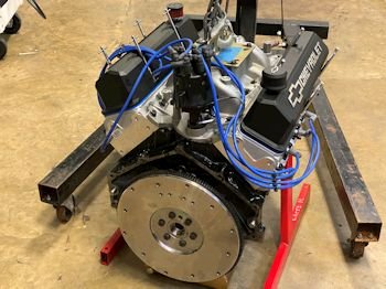
Dyno ready.
|
|