ERE-383 #110
LE2 Heads/Cam
Rebuild and investigate
coolant in oil and no oil pressure
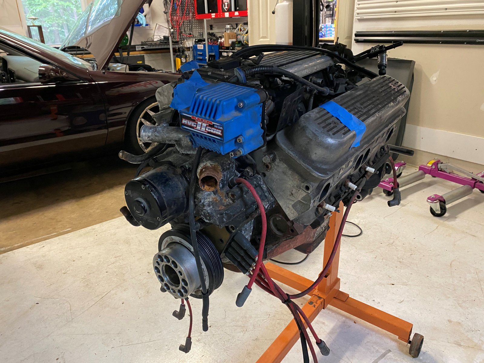
Right now the engine is set up for NA naturally aspirated.
I'll be refurbishing it and investigating for reasons that coolant
is in the oil and no oil pressure and also setting up for forced
induction.
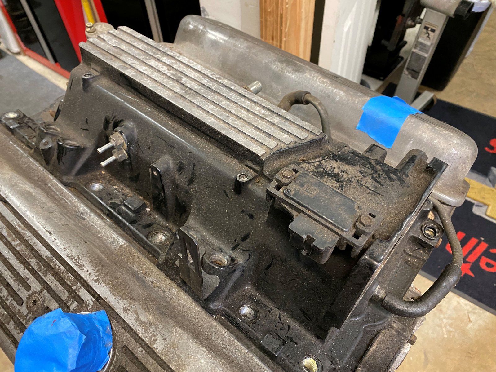
Clean up the major dirt prior to removing the intake manifold.
Very clean inside.
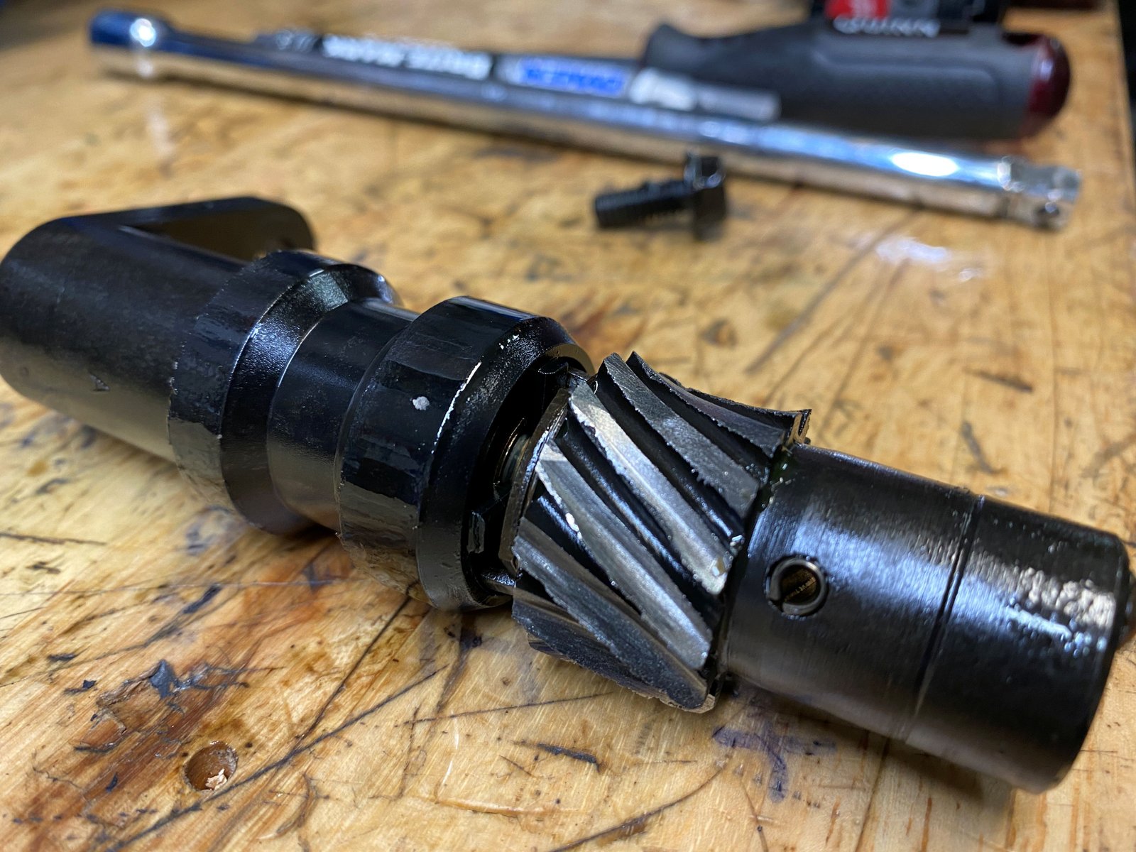
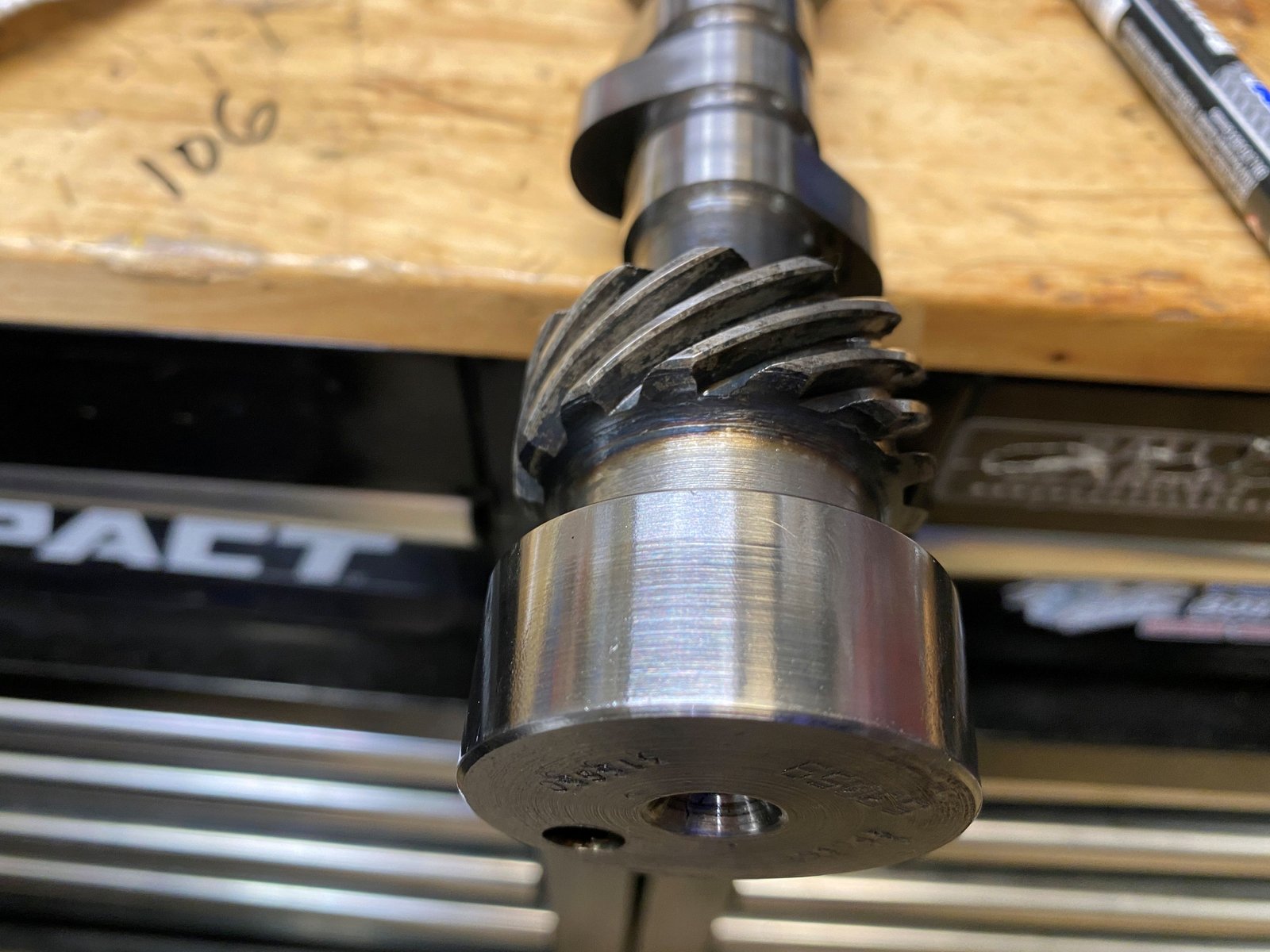
Oil pump drive gear is so worn that there are no gears left.
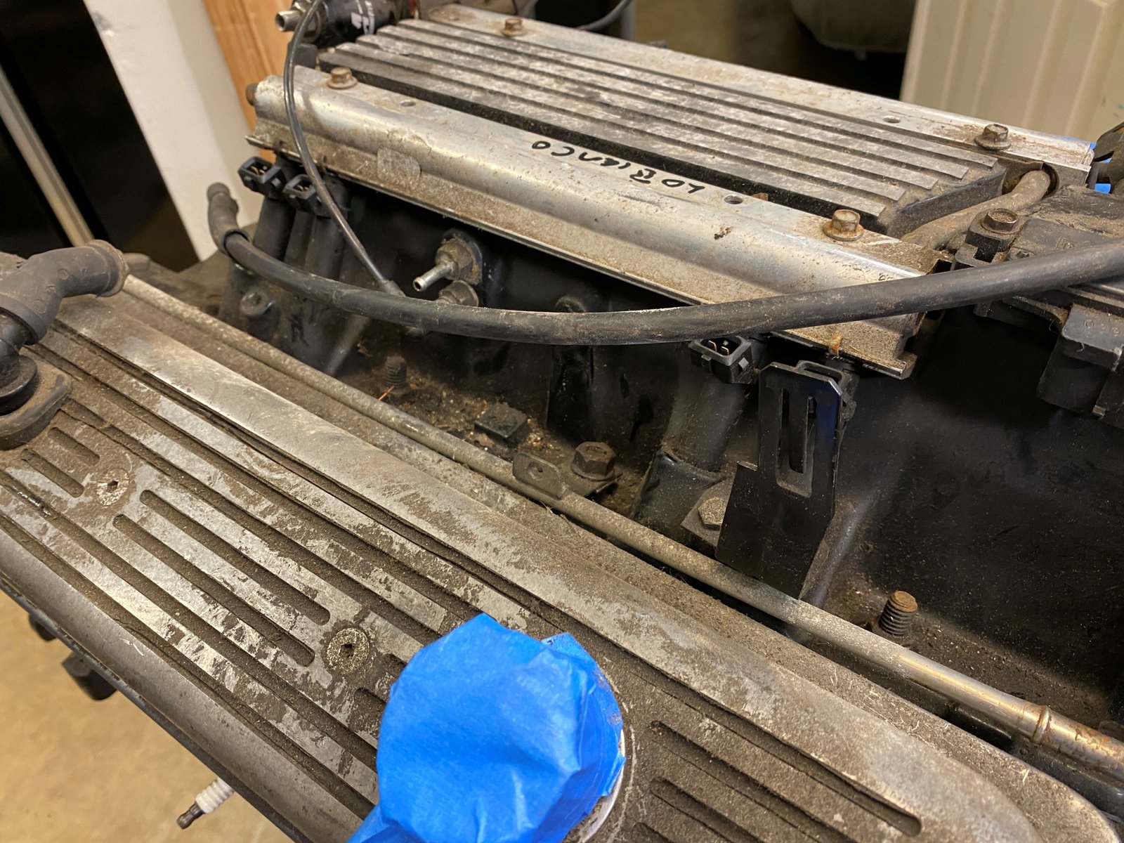
Crower roller rockers. I've never seen a set of Crower
stud mount rockers. Nice!
These guide plates located the roller rocker tip dead center
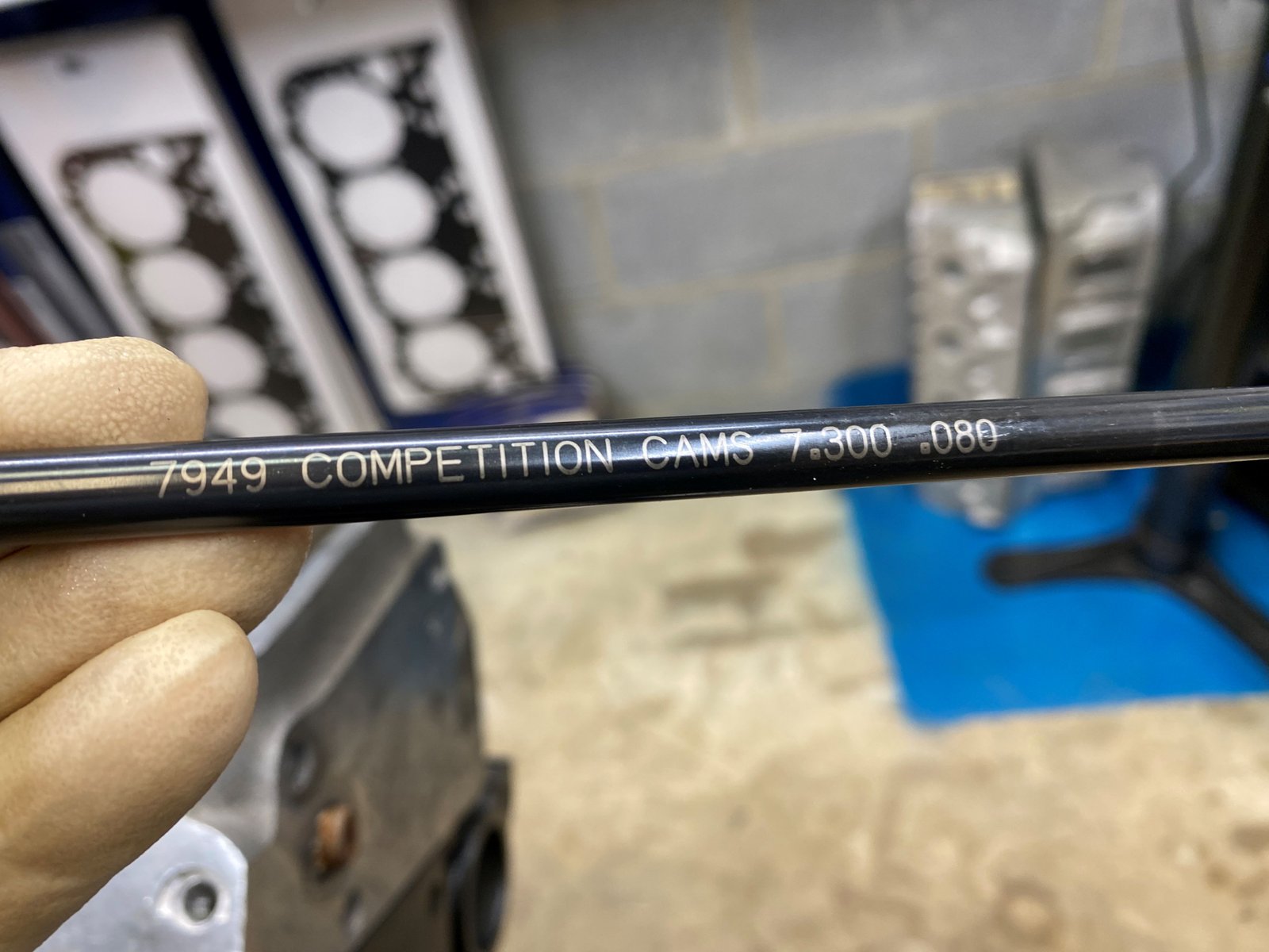
on the valve tip. Pushrods are 7.150"
All looks great.
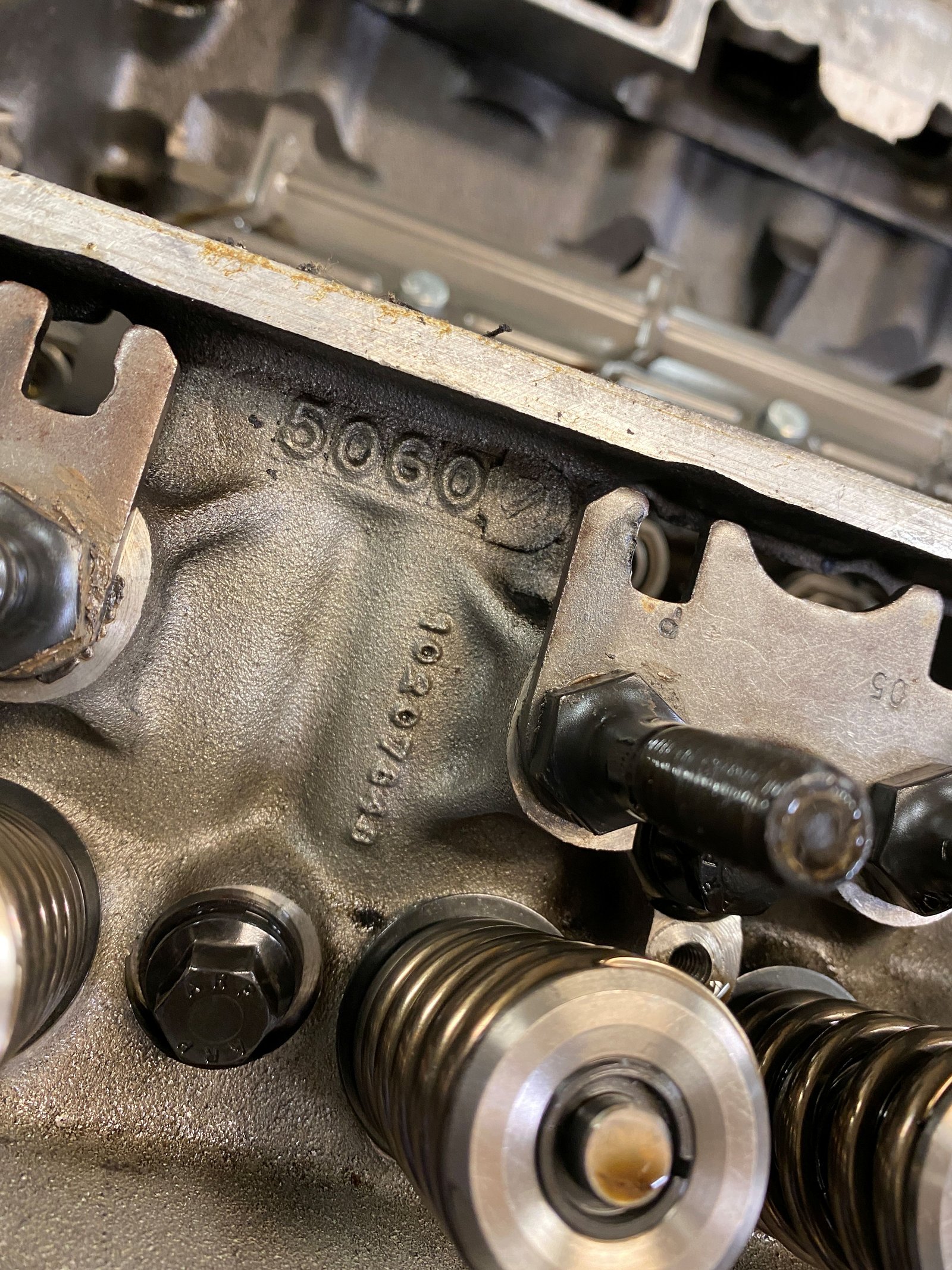
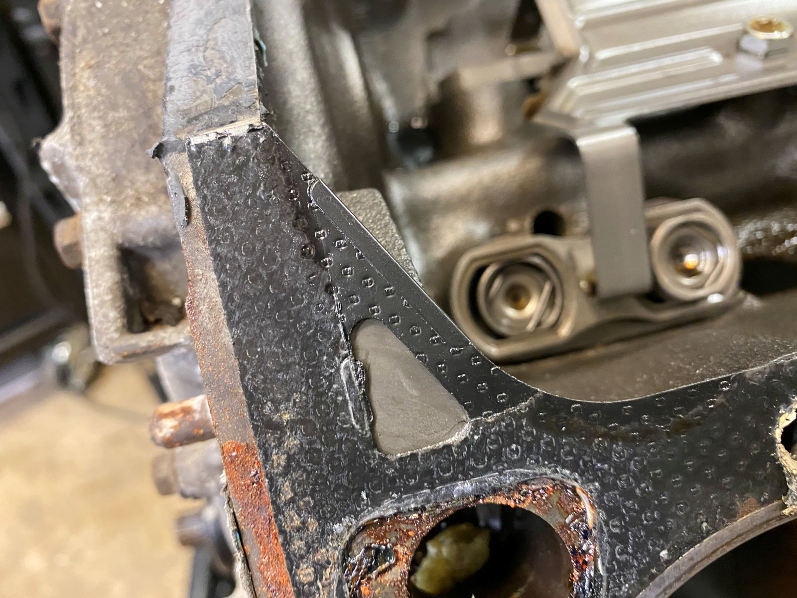
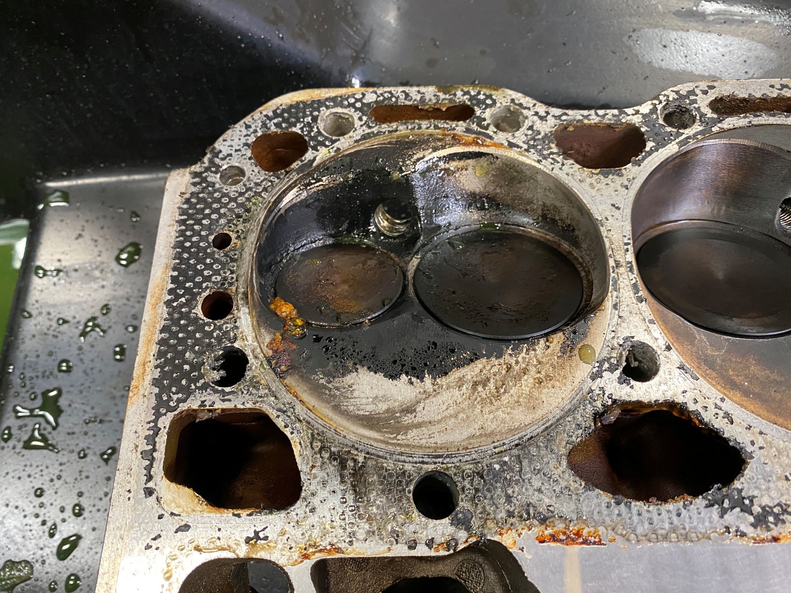
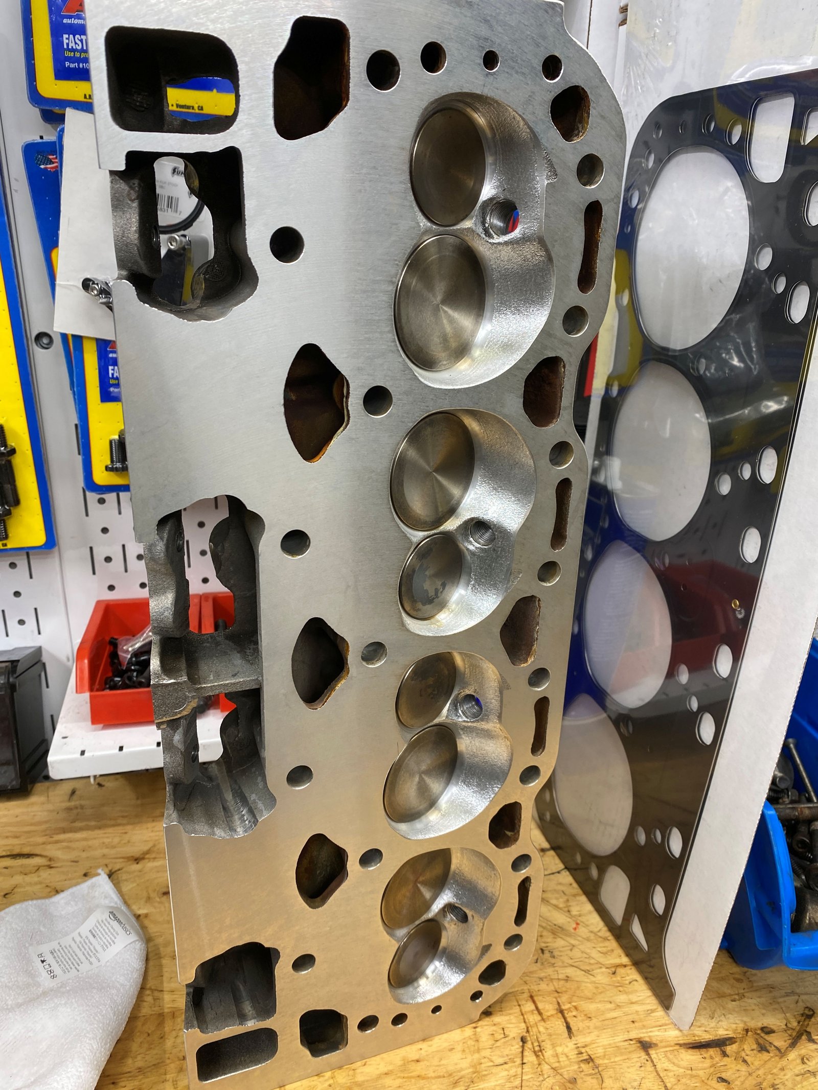
See how the head gasket blocks off oil drain back at the left
(driver's) head.
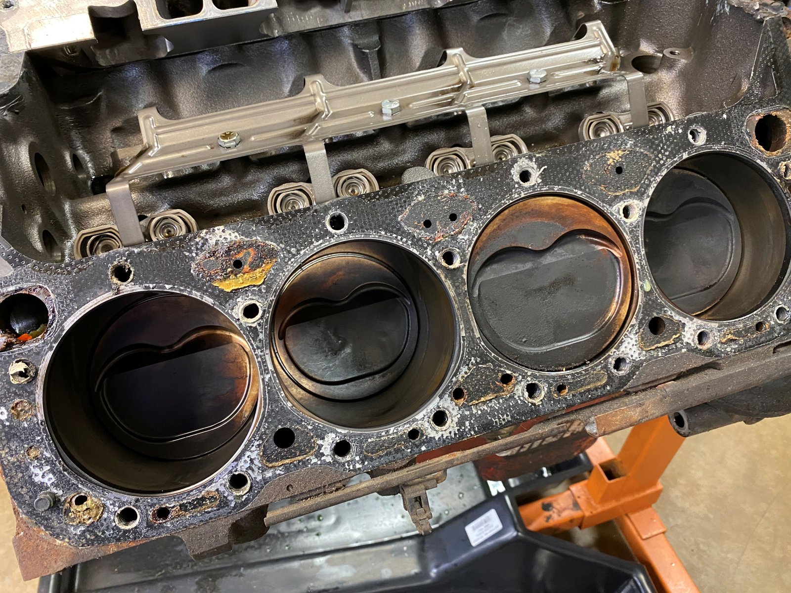
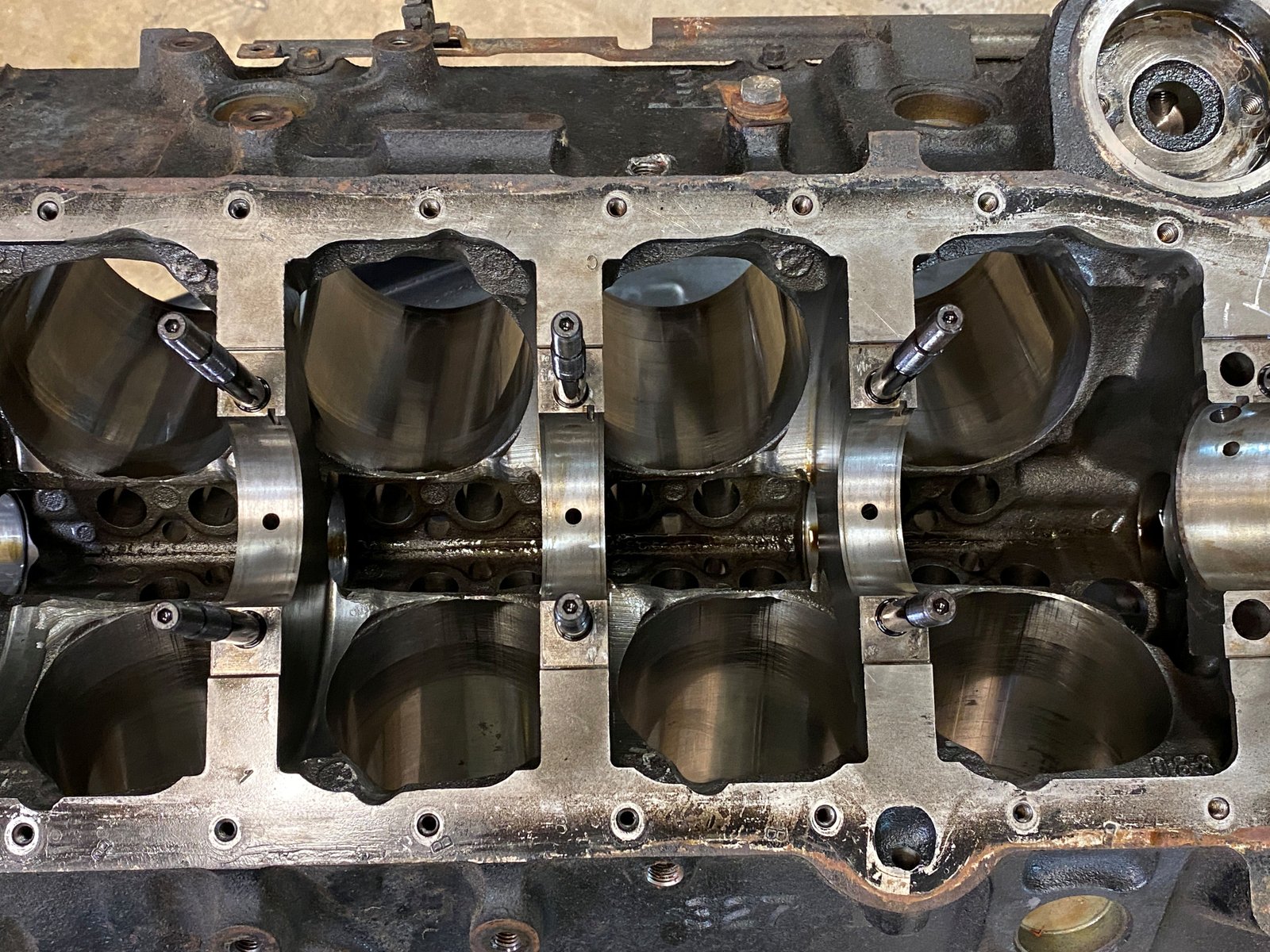
#1, #3, #5, #7 look pretty normal.
#8 looks like coolant from either head gasket or cylinder
crack. I cannot see a crack although there may be one.
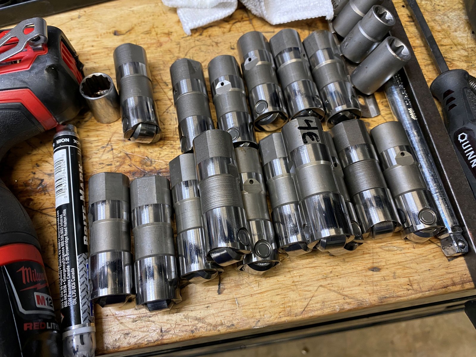
Lifters all pulled out of their bores nicely except #4 exhaust
but it feels and looks like all the others. I don't know the
brand of lifter but they all have #538 lazered onto the side of
the roller. Oh, and one of the 16 lifters is an odd brand.
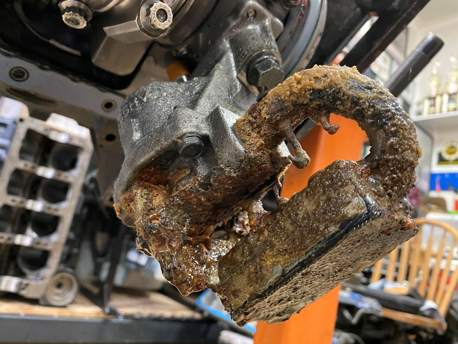
Water in the oil crusted up the oil pump pickup. I still
need to remove the pump and spin the pump to see if it seized up and
caused the oil pump drive to sheer it's gear.
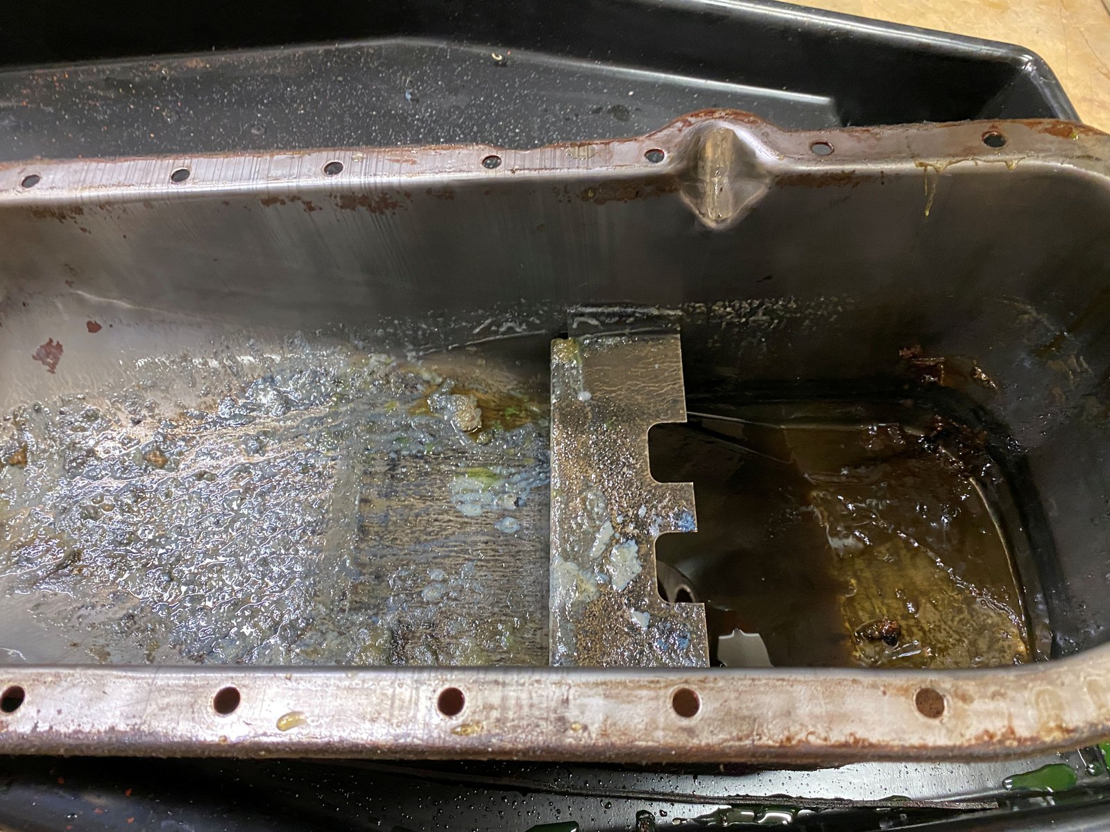
Yucky crust in the oil pan.
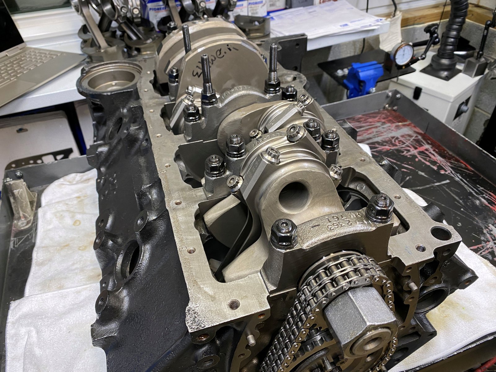
Nice double roller timing set.
Crank sprocket at the zero position.
I like the plugs that were drilled for a tiny oil weep
hole. Kudos and good job to the original machine shop and or
builder.
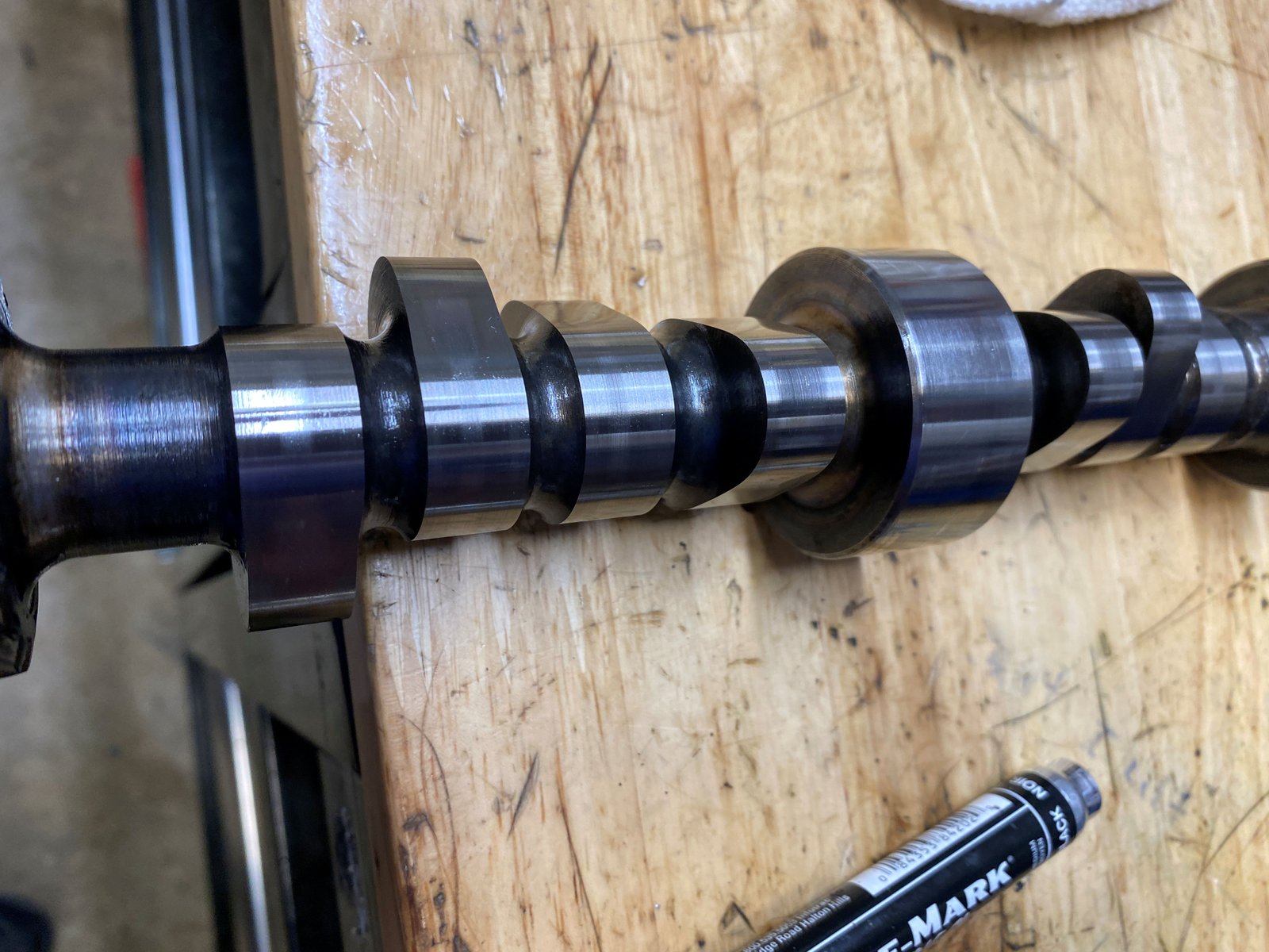
Cam is a billet core. It's in good shape.
Cam bearings are ok too.
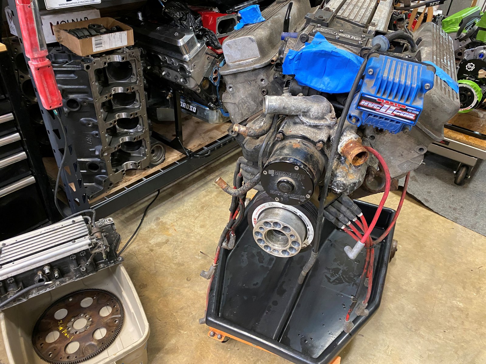
To do: Remove rotating
assembly,
Block to machine shop,
Check for cracks in block,
Hone or bore the cylinders,
New pistons (for forced induction).
New balance,
Refurbish cylinder heads
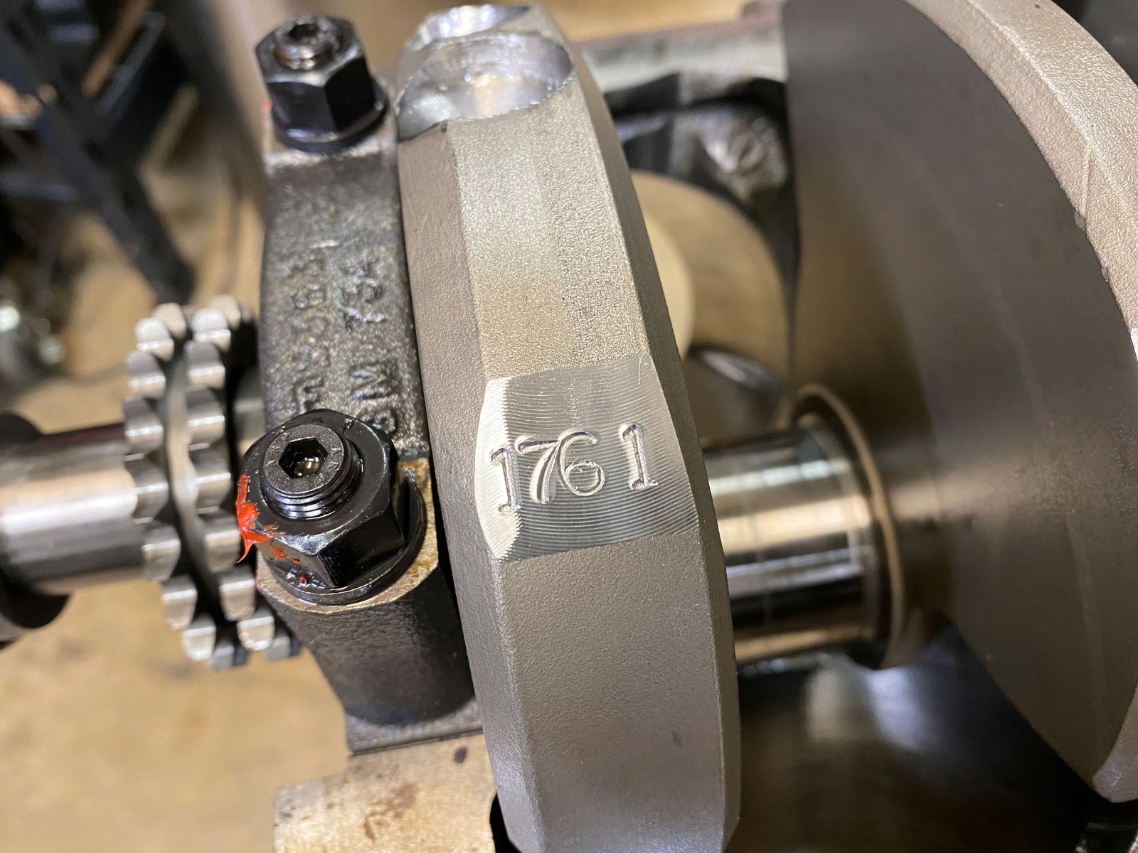
I am easily impressed. The shop that did the balance of the
crankshaft has a neat and clean method to record the balance
bob-weight.
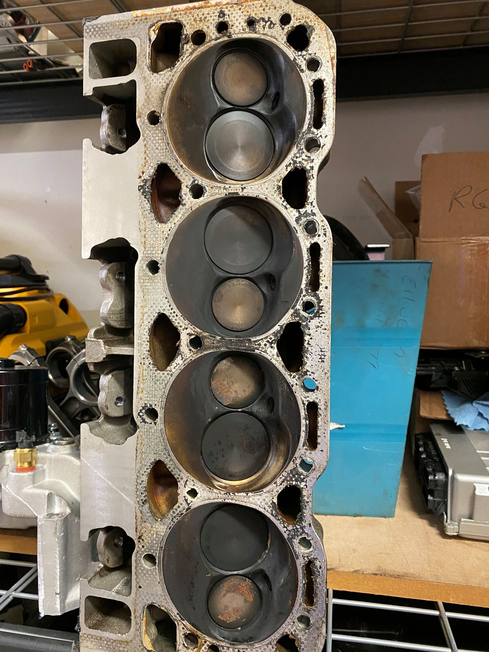
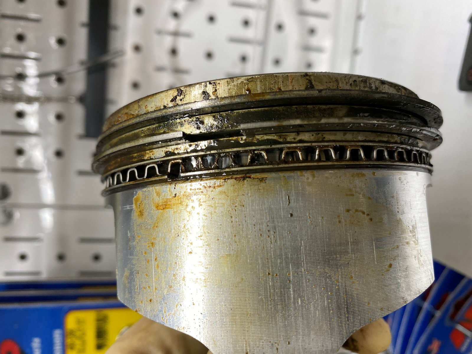
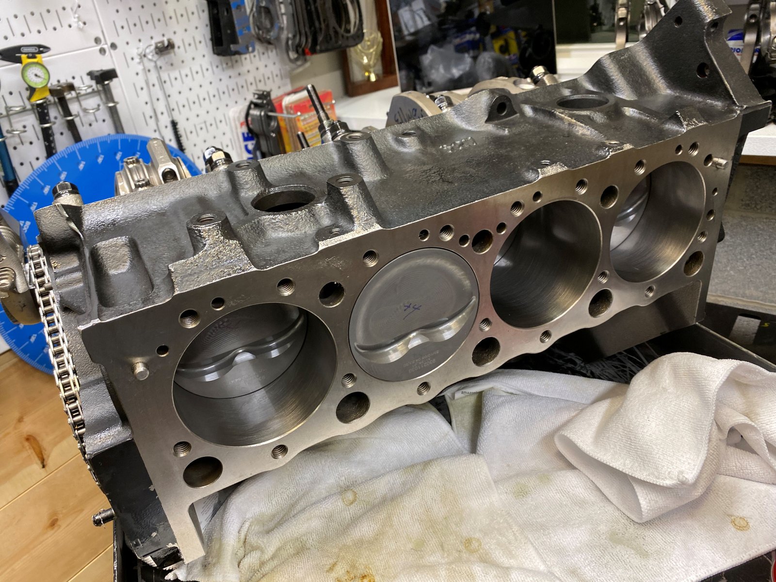
This is piston #8. For now I think there was a slight head
gasket leak. Little leaks make big messes. Head and
block testing will verify all is good with the heads and block.
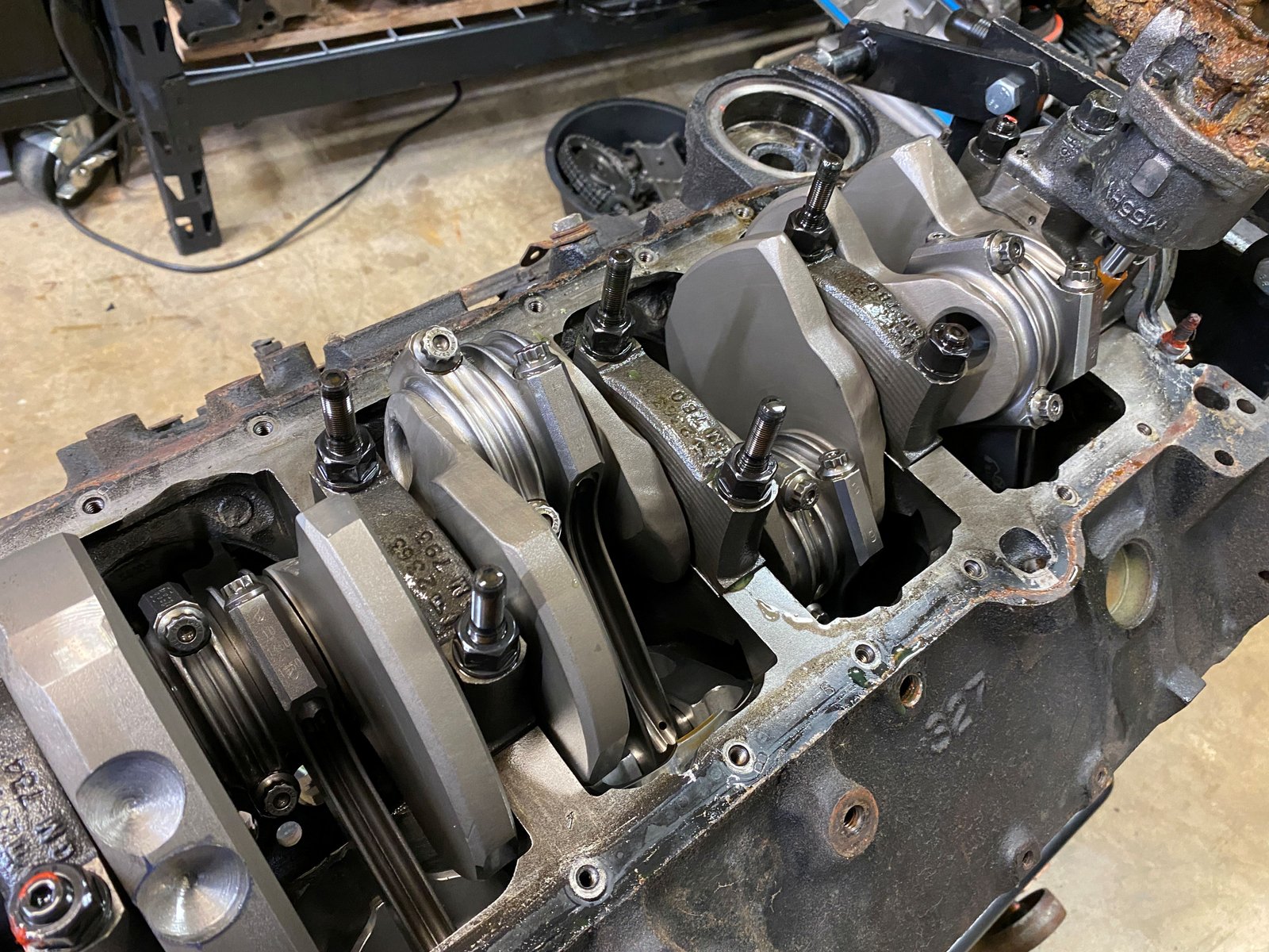
Rod bearings are typical for having coolant contamination and some
dirt. But also there is more bearing pounding than
usual. The top bearings on the LEFT bank (1,3,5,7) are worn at
the top as if there was some or occasional detonation.
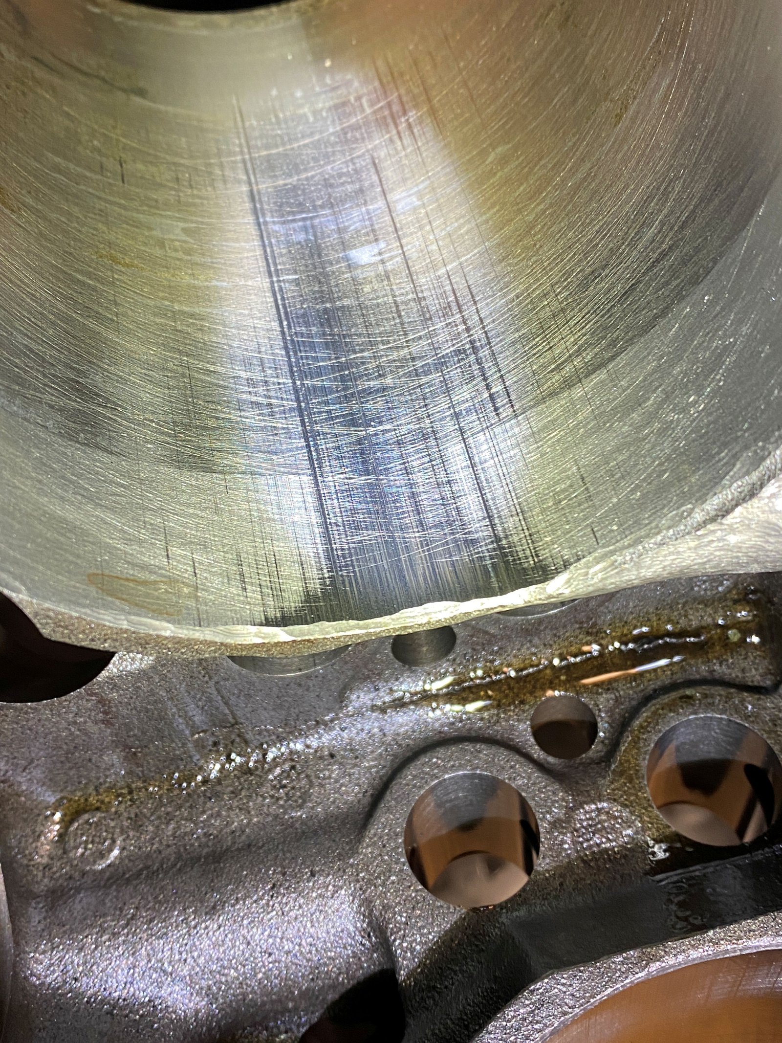
Stock main caps are not the most stiff but this is the most
crank-walk I have ever seen. Crank-walk is pitting or cavitation or
micro welding.
So I'll be talking to my machinist friends for advice on
this. Was this caused by tune up? By tune up I mean
detonation or just too much power for the caps to hold the crank
firmly.
Main bearings Ok with the typical dirt/coolant contamination.
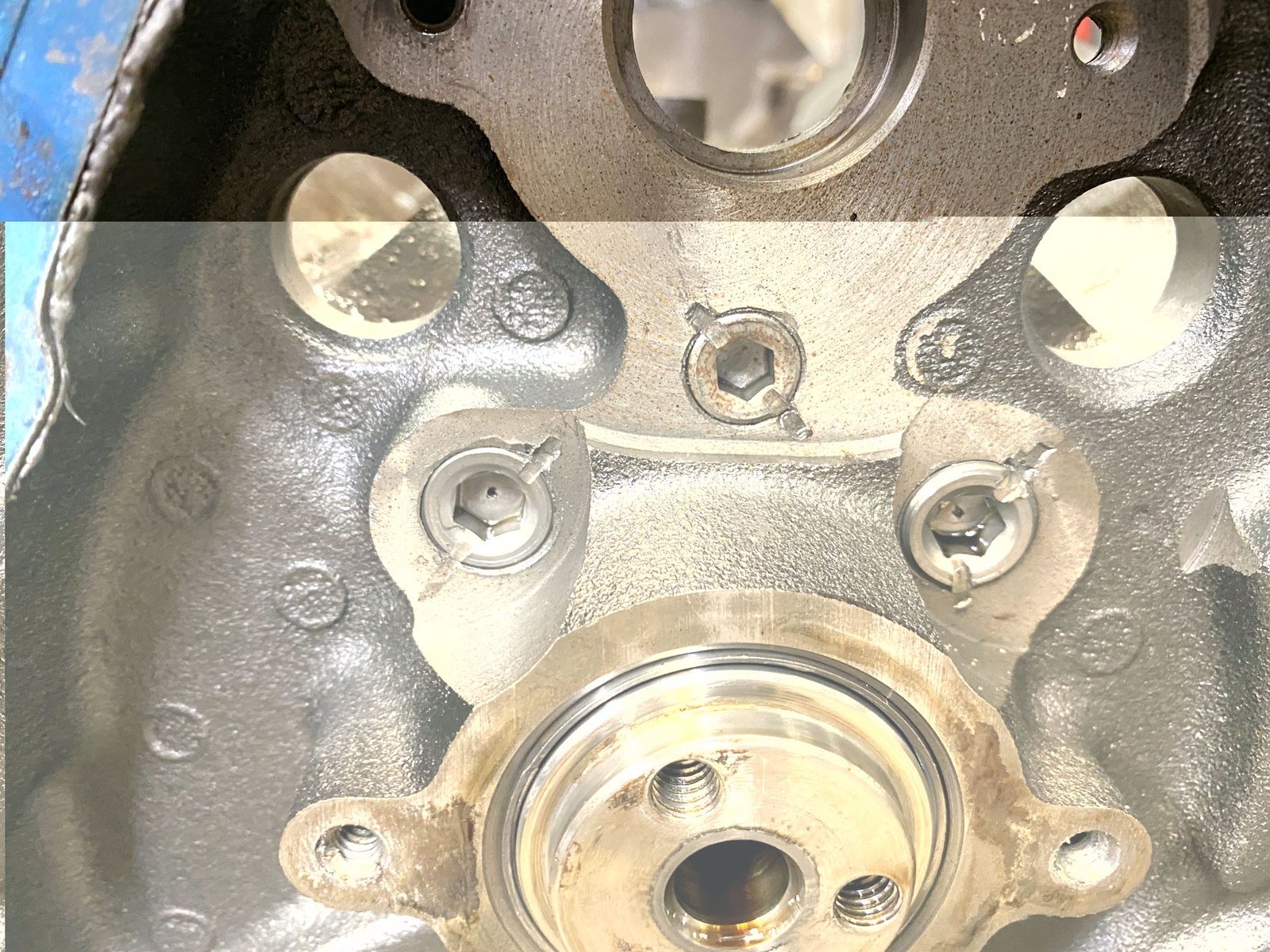
Different views of cylinder #8. I don't see a crack.
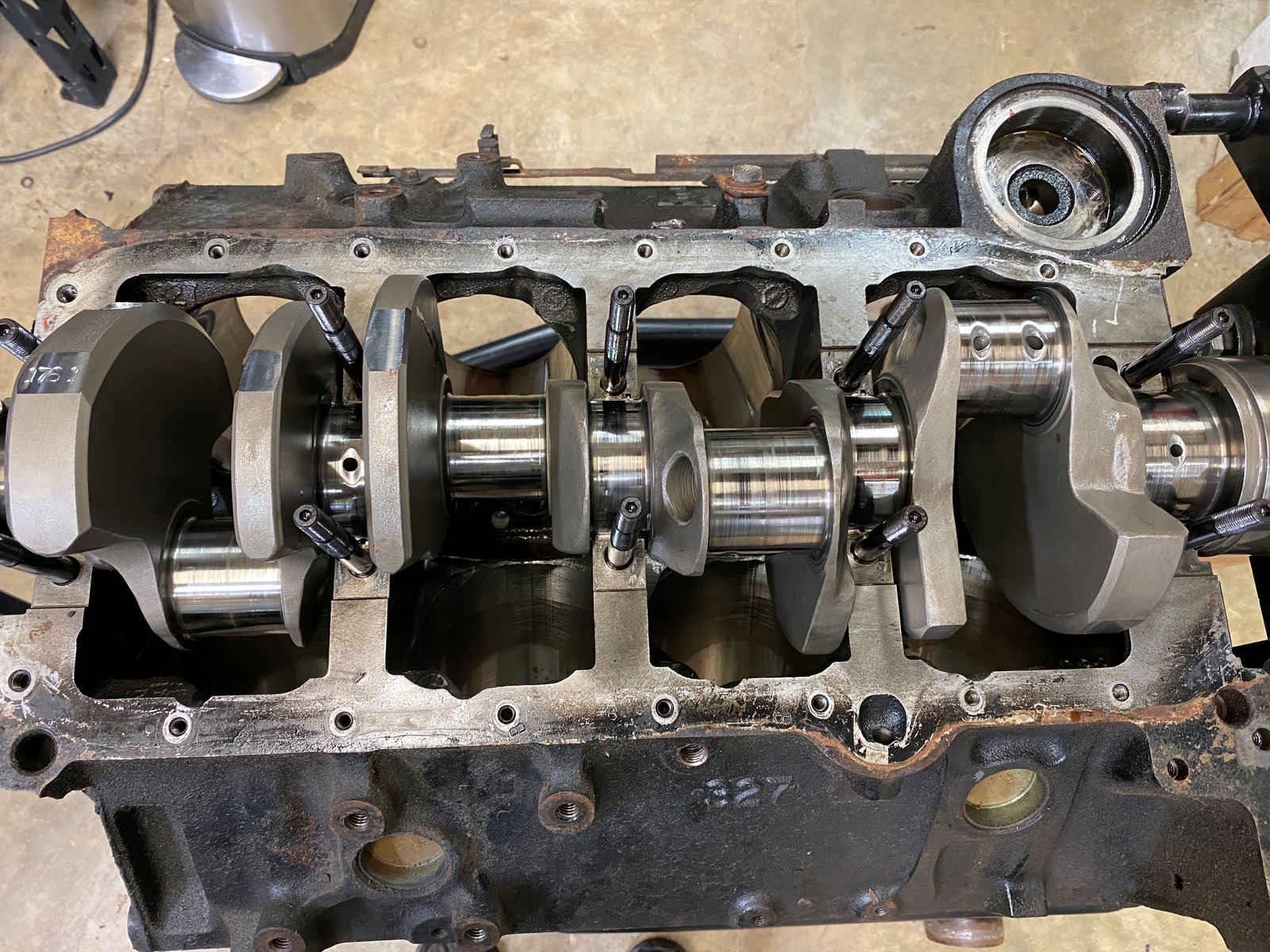
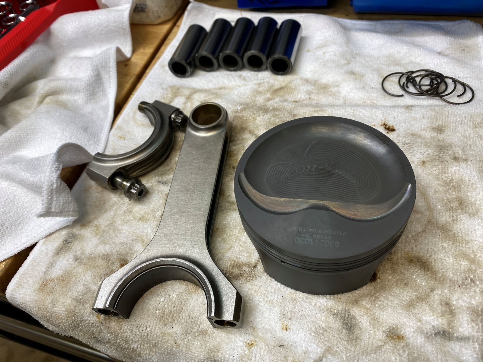
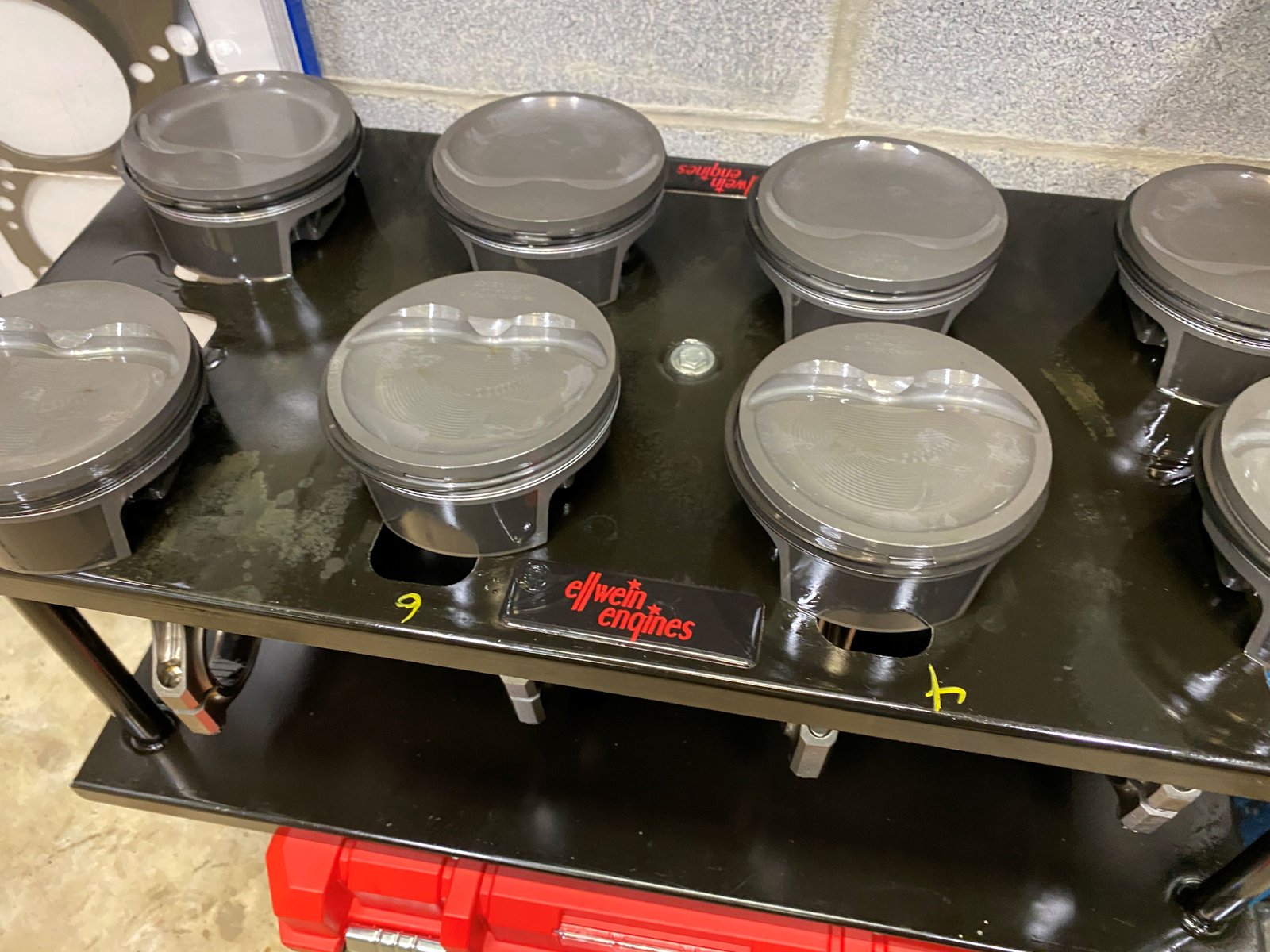
Now it is a few months later and the one thing I've been waiting
for has arrived, that is the new pistons. They are the Mahle
-28cc dished piston #930211030. The block is "new"
too.
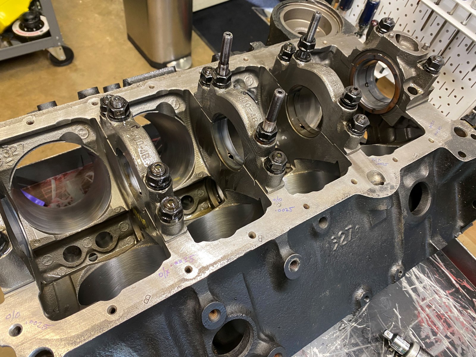
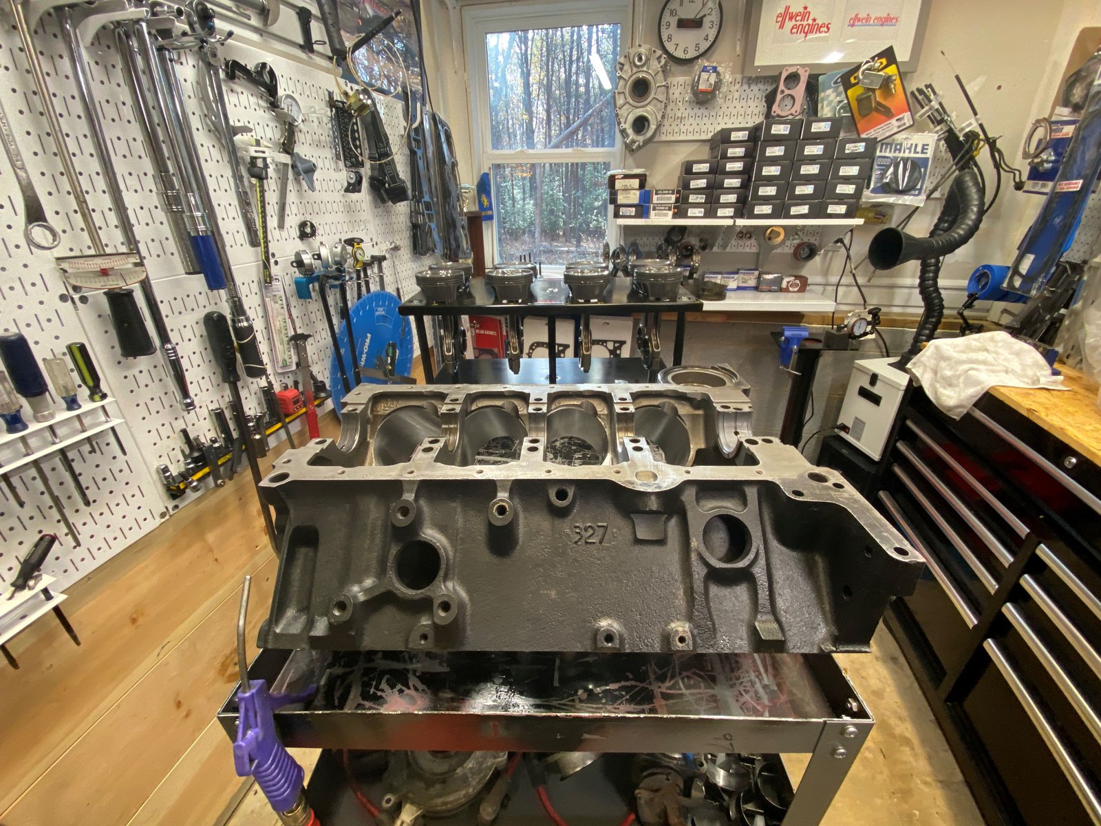
The block is from Golen originally. I've had it on the
shelf stored as a spare. The caps are not "steel or
billet" but they are 4-bolt similar to a GM 4-bolt. ARP
studs are used too. I swapped out some of the studs in place
of tall windage tray studs.
Since this is a forced induction application I made sure to give
a bit more bearing clearance in the mains. .0025" to
.0030" using King 557XP (standard and X mix).
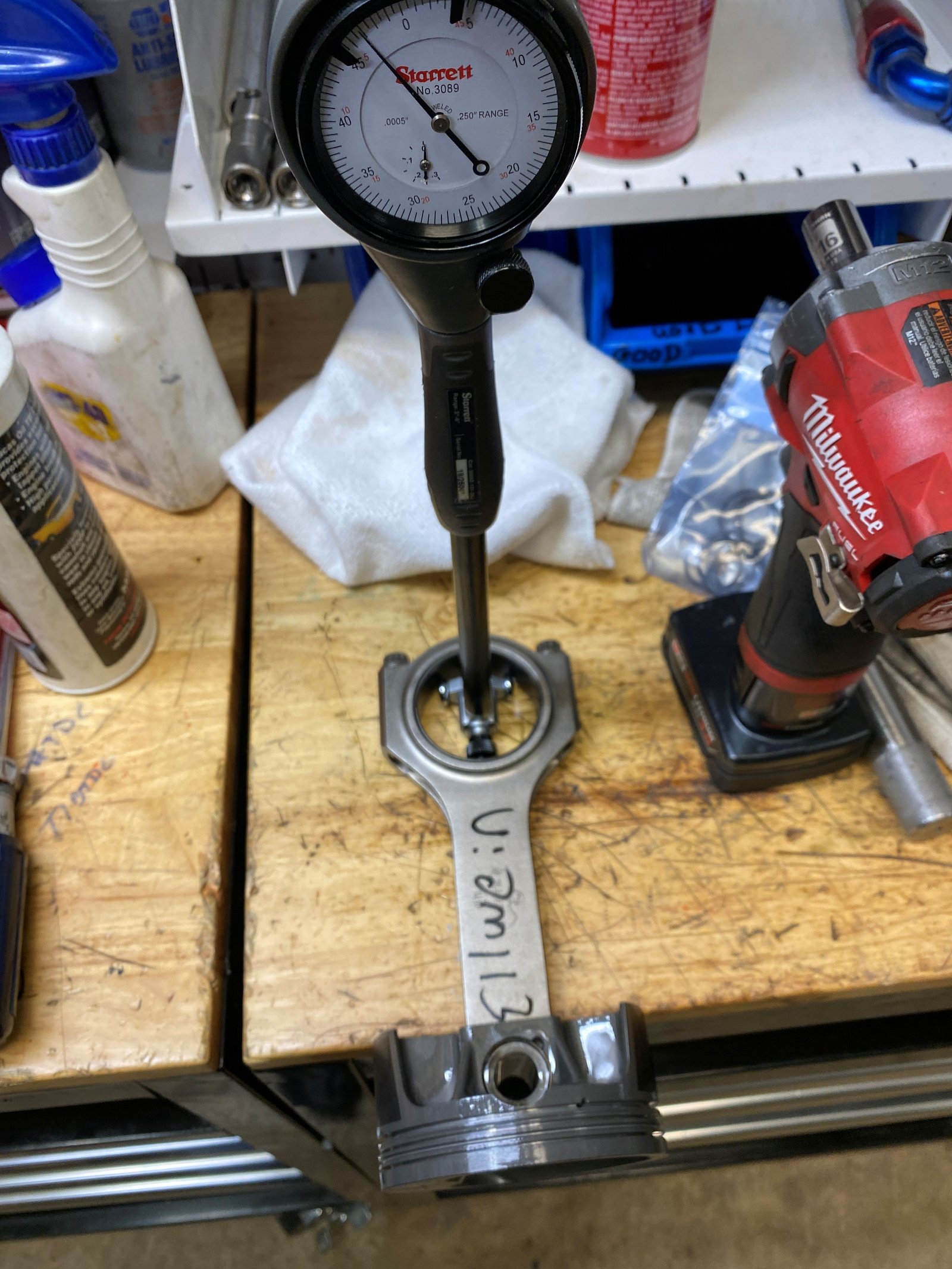
Each rod bolt is carefully checked for .0045 to .0055"
stretch at 65 ft-lb. They are used rods and so it is wise to
take more time to inspect them. These do seem to be as good
as new. Eagle brand 6" H-beam rods.
Rod bearing clearance is generally .0025" using standard
size King CR807XPN bearings.
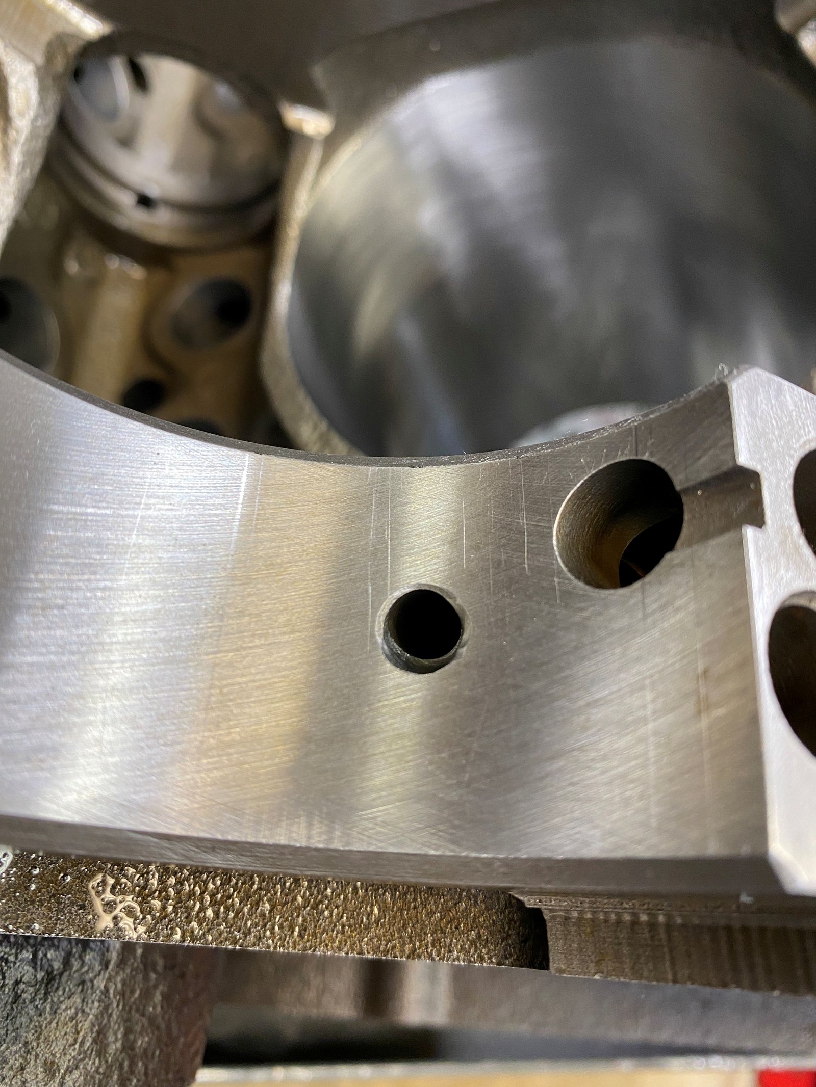
This turns out to be a pre-assembly of the crank/rods/pistons
(as opposed to a final assembly). The rod bolts are very close
to the block and in one spot the rod bolt touches. The whole
rotating assembly will come out and the block will be clearanced and
cleaned and then reassembled.
Each area here is close to touching the rod bolt.
Cleaned up after doing more clearance work. Click the
photo for the larger version.
Another view.
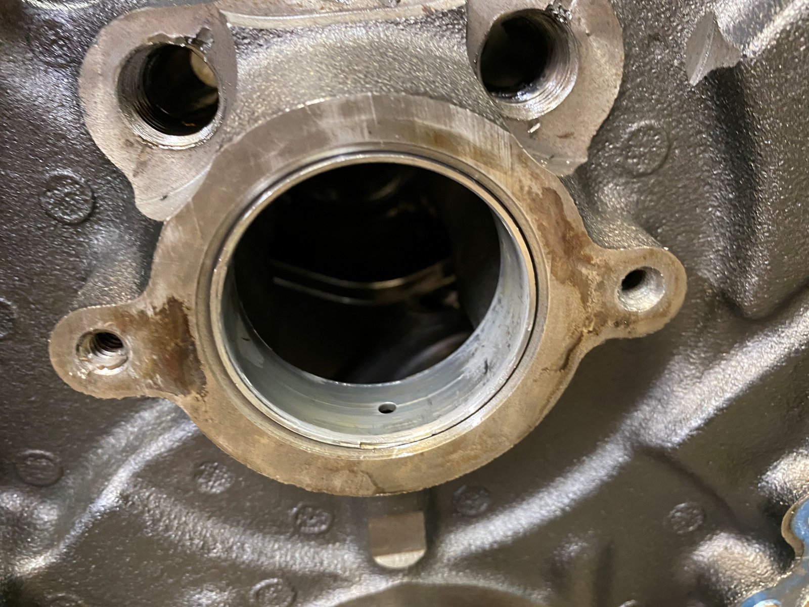
The rear main oil hole does not line up with aftermarket
bearings. I usually make the hole wider as shown in the photo.
Shop fisheye view. Getting ready to install the new cam
bearings then camshaft and timing set then crank and rods and
pistons.
Forgot to mention for my records...the crank bobweight is 1785g
balanced by Chris at Clinton Machine.
451g piston/118g pin/2g locks/21.5g rings/43g
bearing/188.5g-457.0g rod/4g oil
Pistons all have rings on after I gapped the rings to .028"
top ring and .028" 2nd ring as per 15 psi or higher forced
induction recommended gap.
Bores clean and oiled and ready for rings.
Bottom end fully assembled.
Measuring how far in or out of the hole the pistons are.
Pistons ended up being .004" OUT of the hole. This
block has been "zero" decked.
Melling 10554ST oil pump. High pressure, standard volume, 3/4"
diameter pickup.
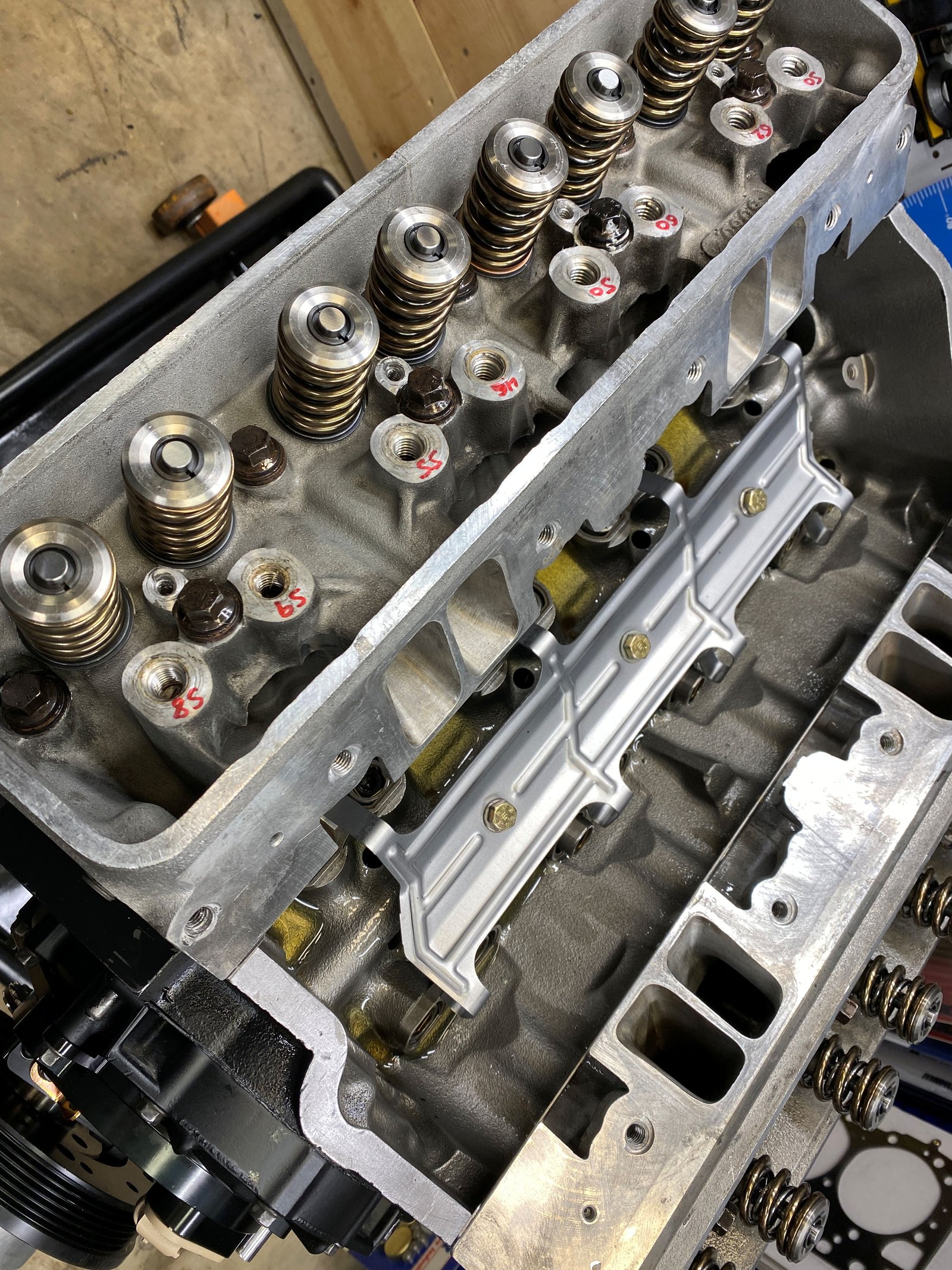
Windage tray added. (donation). Bending the tray out of the
way of the rods.
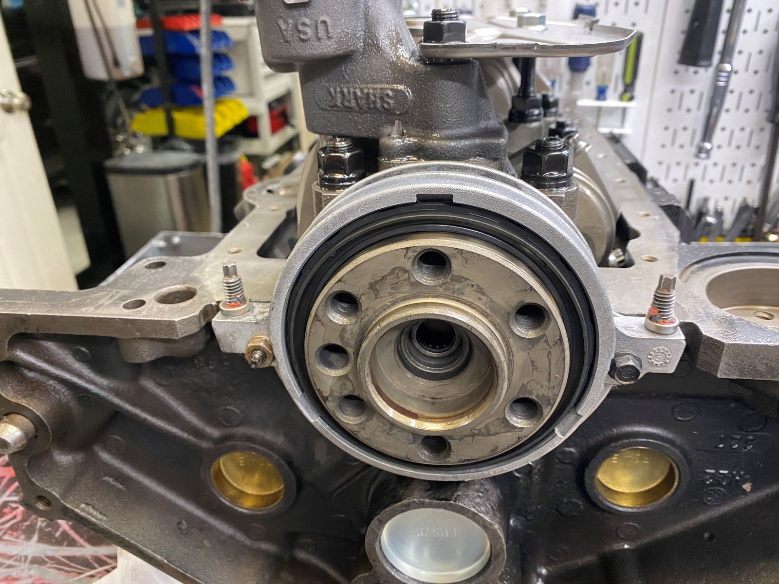
Rear main seal housing centered with .004" feelers.
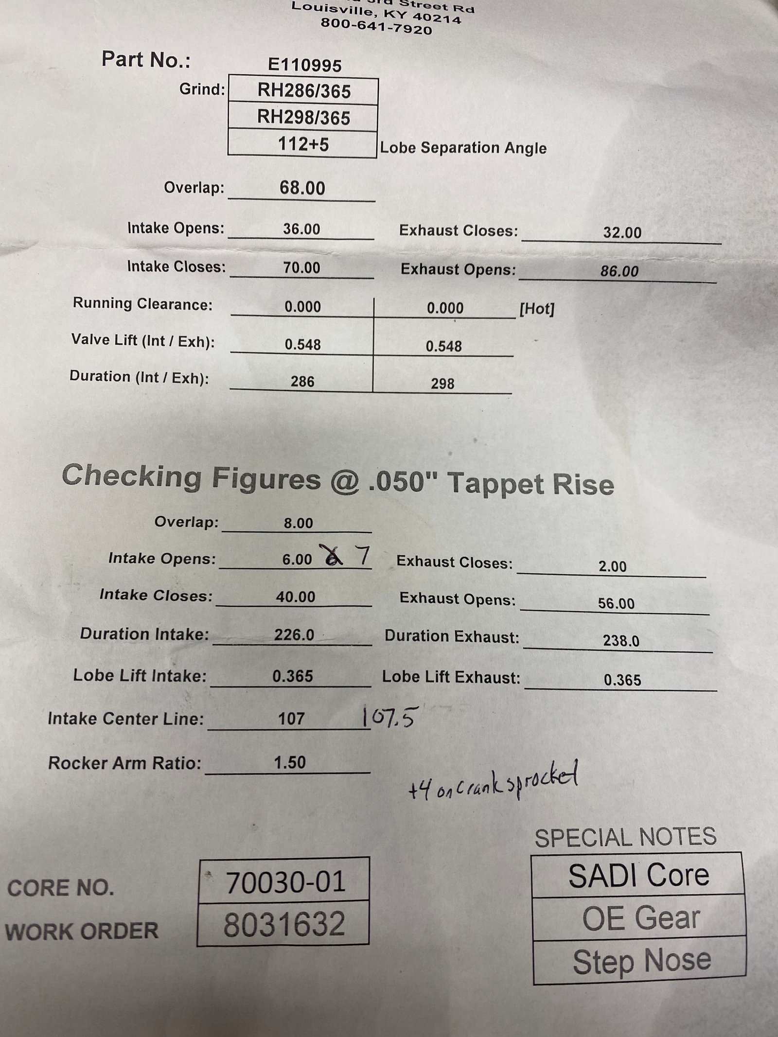
Cam was 112 intake centerline with crank sprocket at zero.
Then went to +4 position and it came right in.
Oil galley plugs have weep holes.
The timing cover was very dirty. I cleaned the aluminum and
spray painted it flat black.
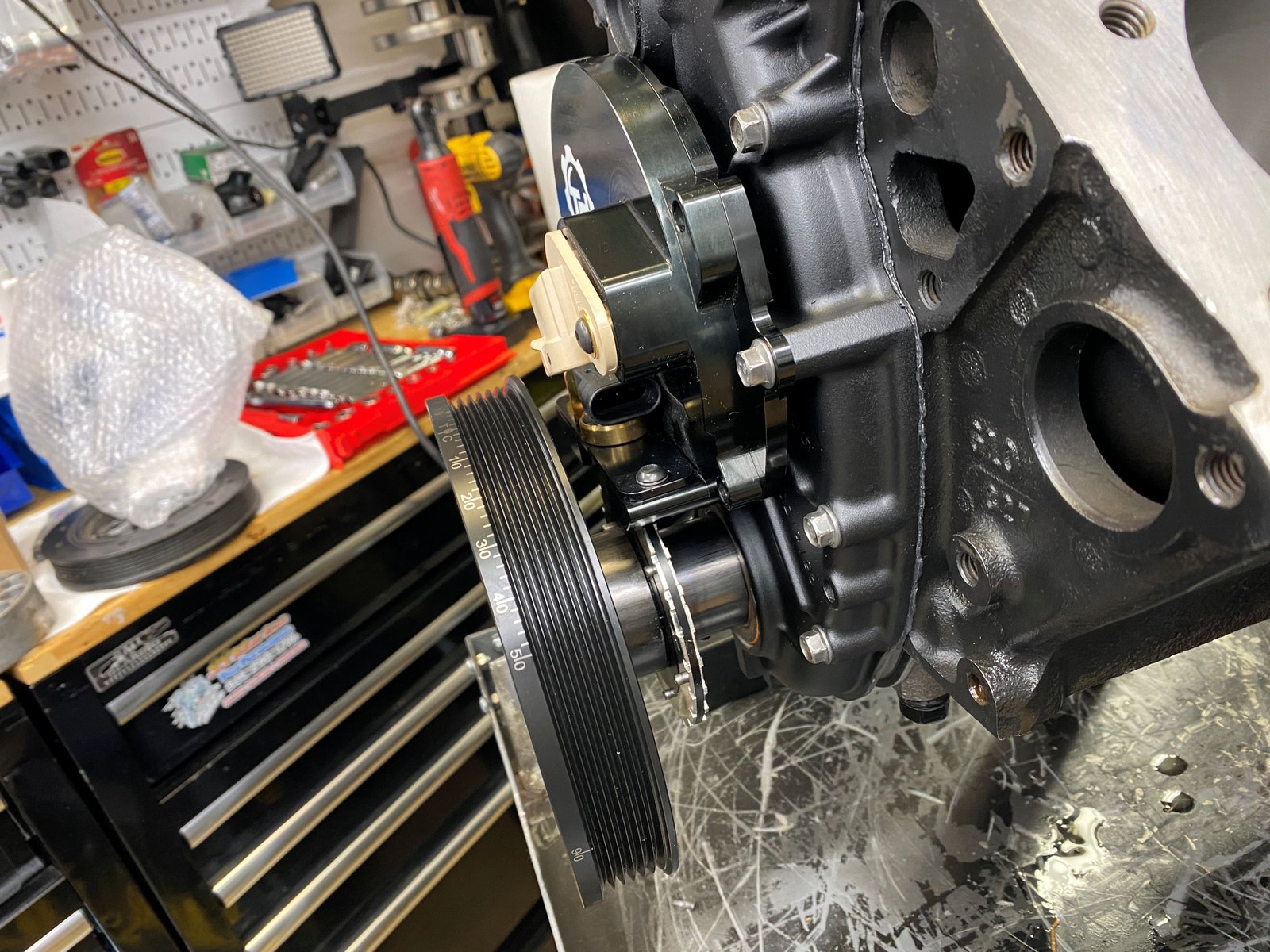
The power bond damper on the right and the owner's ATI hub and
damper on the left. The 24x hub is quite a good quality piece.
The Powerbond damper is SFI rated too. I think the Powerbond
is as good as the ATI.
The spacer was added to take the place of a reluctor prior to
installing the hub and damper.
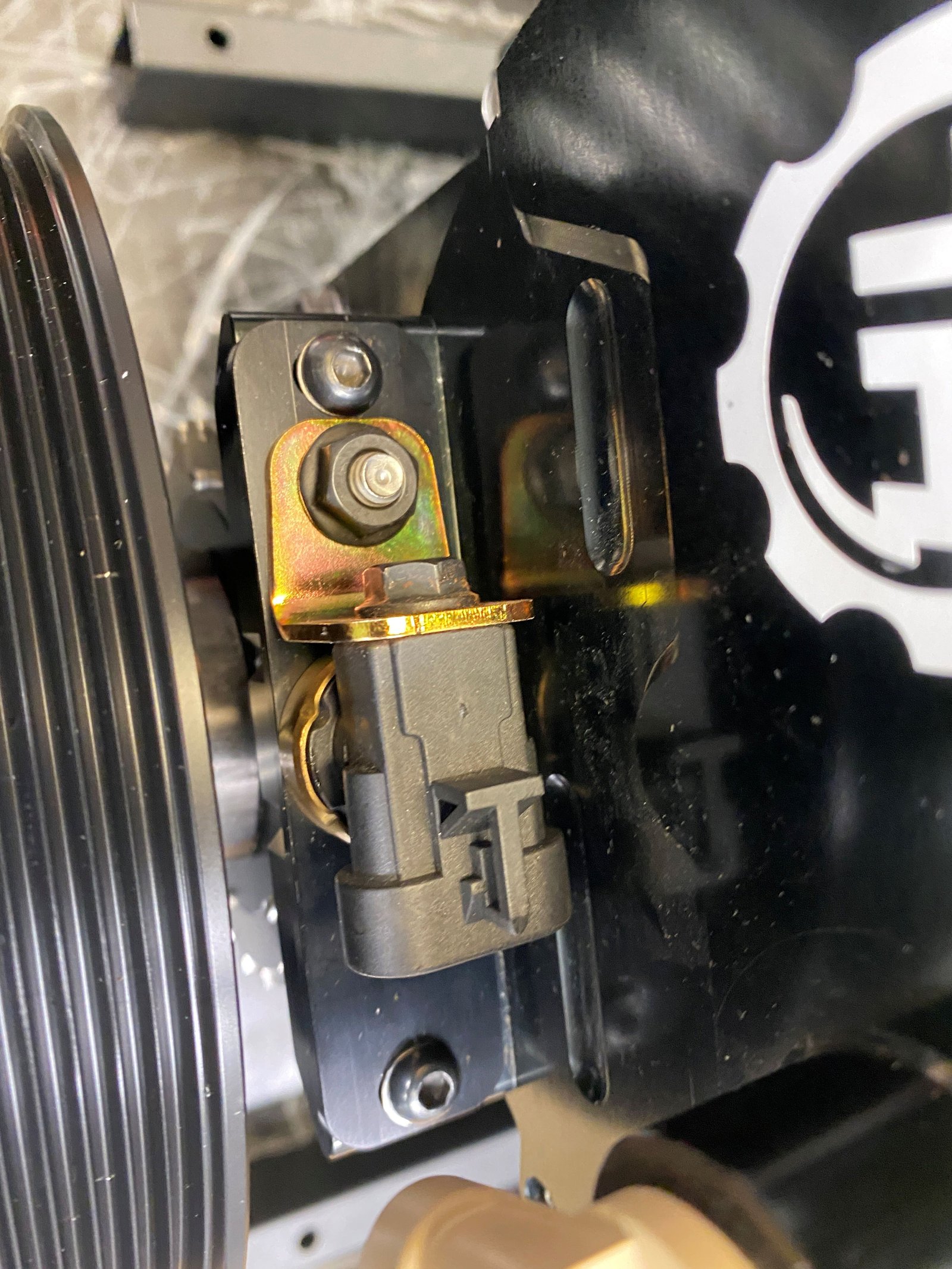
Centering the TorqHead sensor housing.
Found a great timing pointer.
Summit 163638.
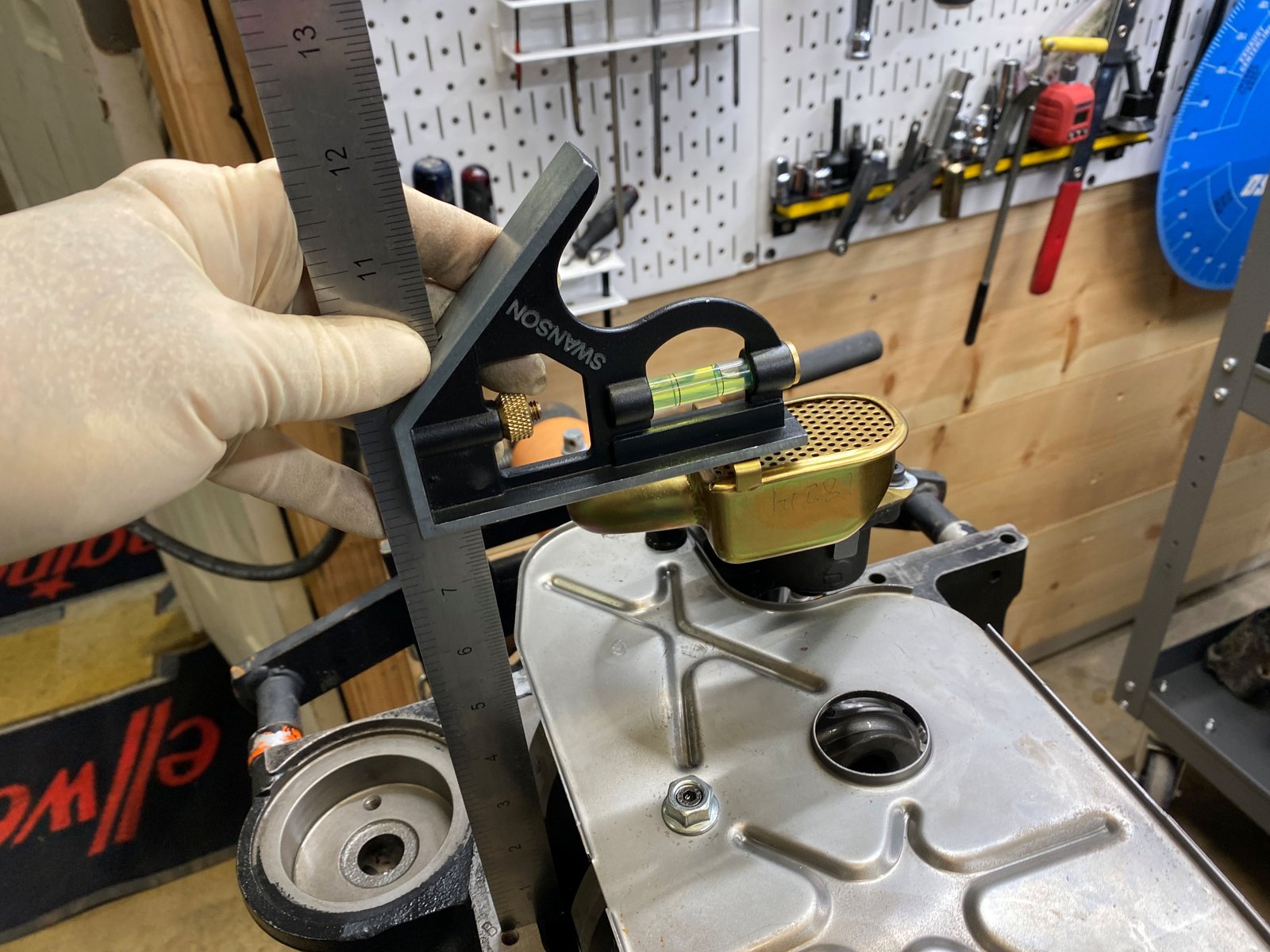
Oil pump pickup on. Then I realized the oil pan is
8.25" deep. I should have checked. This pickup won't work. I'll save
this oil pump and pickup combo for some other customer.
I have a stock of various pickups. This one is for 8.25"
pans. Should work fine.
The things you have to watch out for as a builder. Parts
that are in the wrong box. I grabbed a new 10554ST pump and
a Melling 10555 was in the box. Good thing I had a 3rd Melling 10554ST to pick from.
New pump and pickup is exact at 8.00"
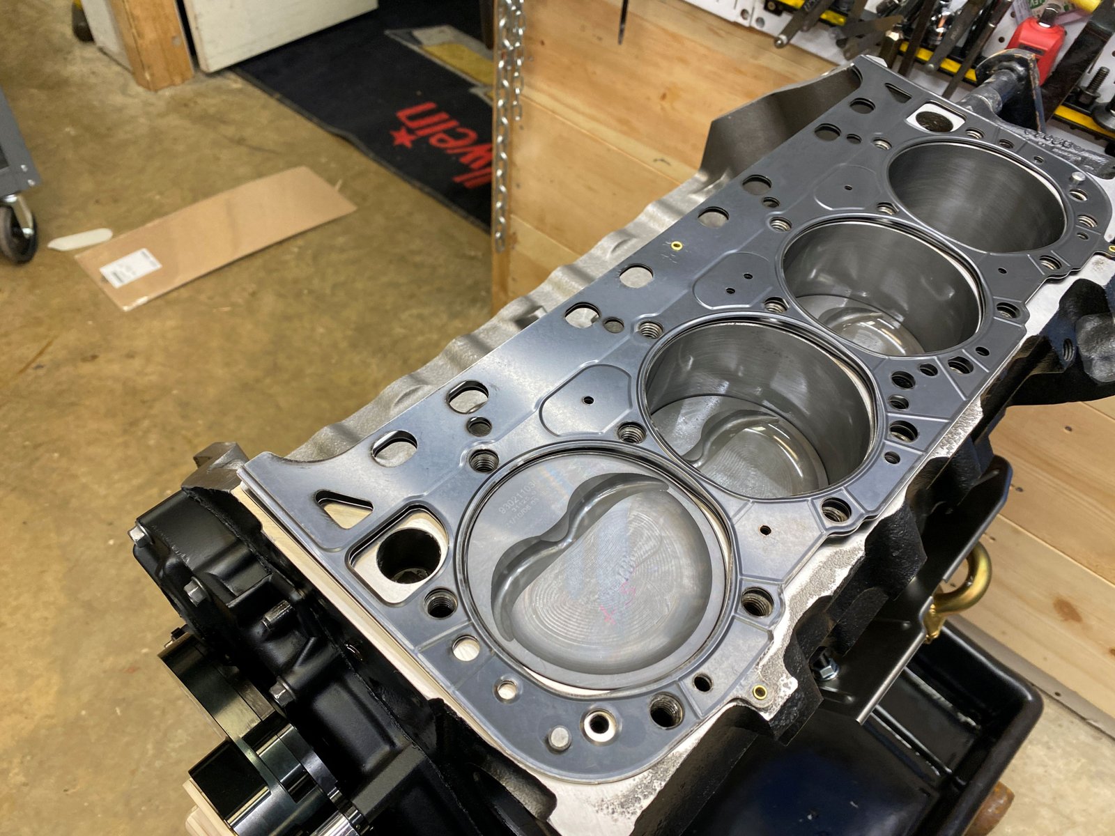
Now installing cylinder heads. Going to use a .040"
head gasket since the pistons are .004" out of the hole.
I stocked up on various size Cometic head gaskets last year.
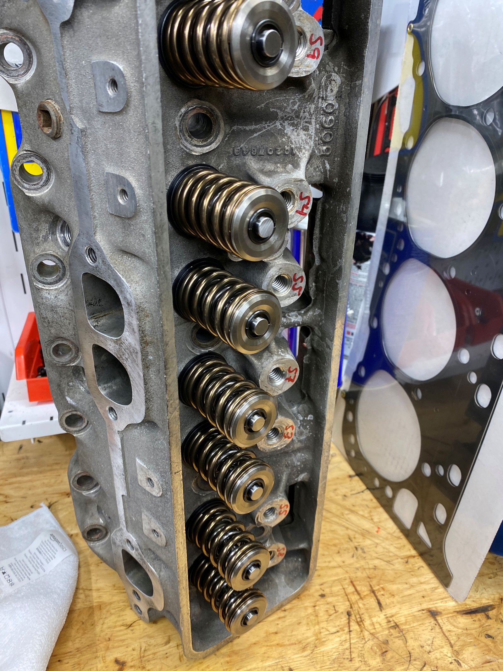
Photo of the driver's side cylinder head
It was refurbished by Dennis Staff.
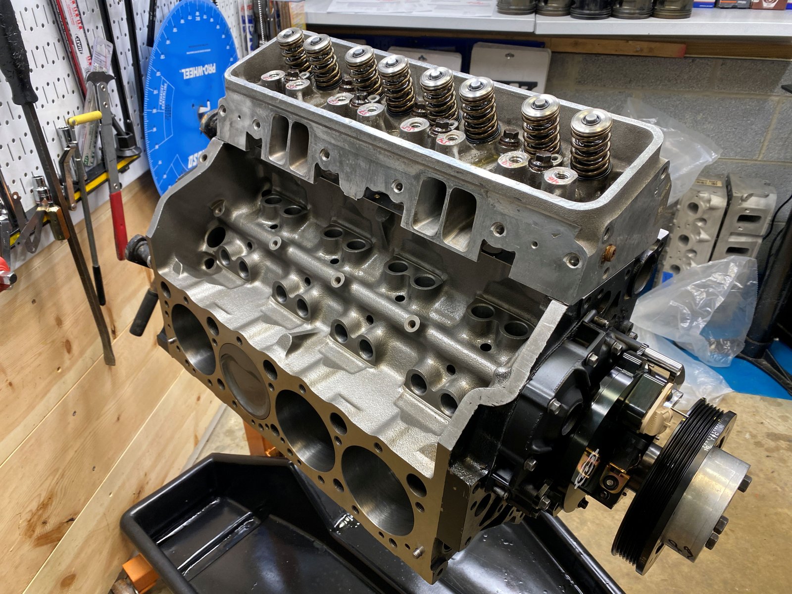
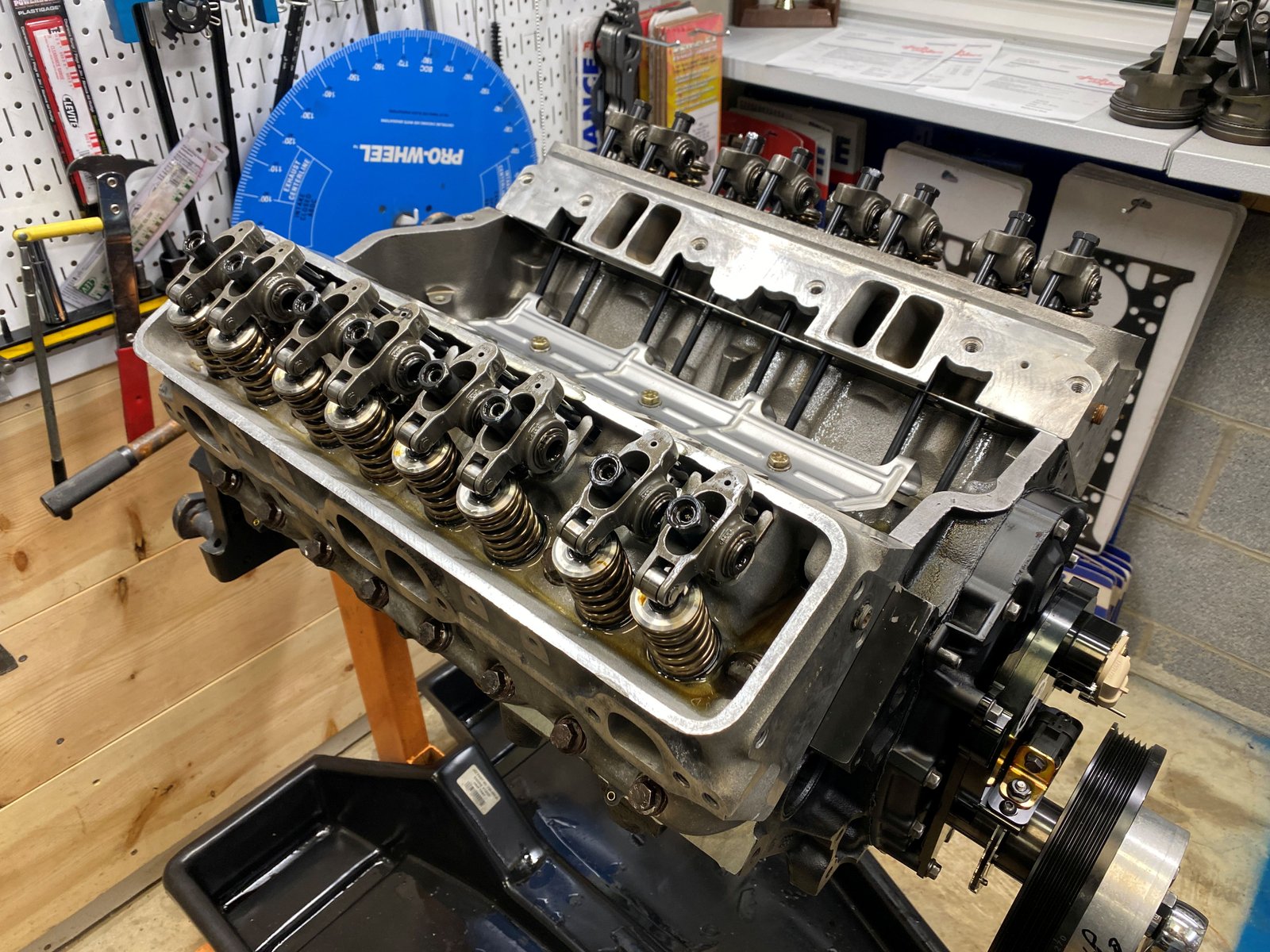
Heads going on.
Nice LE heads refurbished by Dennis Staff at Fast Cat Porting
Services.
Passenger side.
GMPP lifters #88958689
Turns out the 7.300" pushrod gives the best rocker tip
sweep. The engine did have a 7.050" pushrods and that
was not usable.
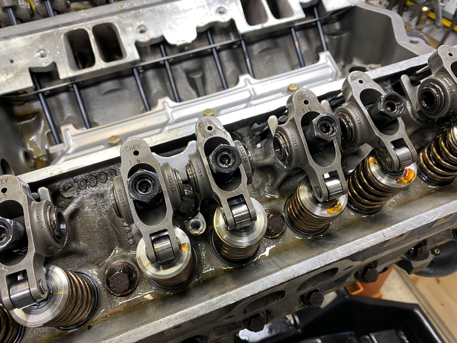
The lifter guides don't align the rocker tips perfectly but
that is typical. The rocker tips are right on center with
some valves and "close enough" with others.
Crower rockers 1.5 ratio
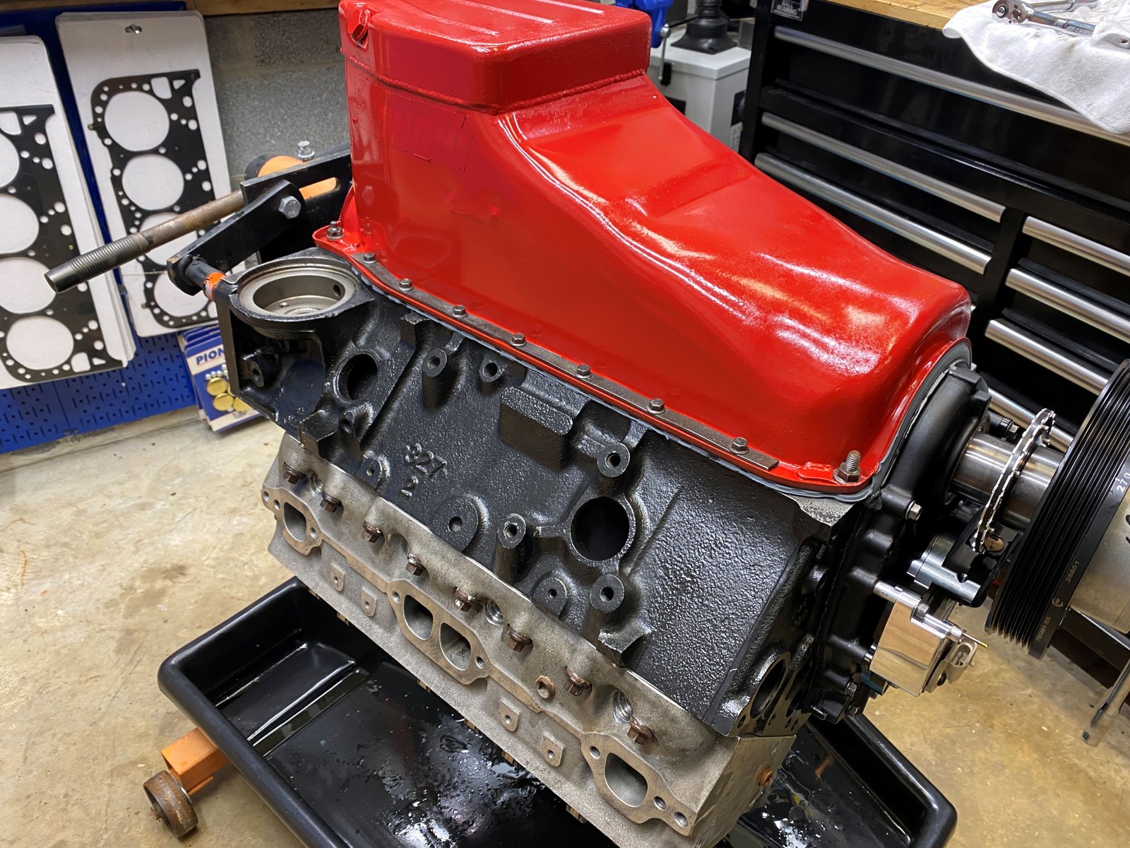
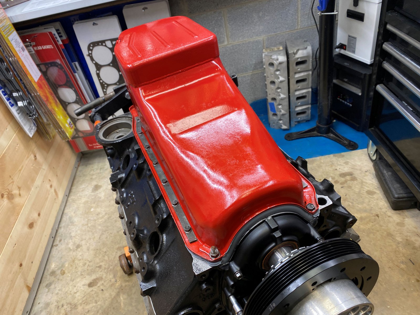
Moroso oil pan cleaned up and painted red. I'm gonig to put an
EllweinEngines decal over the Moroso sticker.
Dyno Results
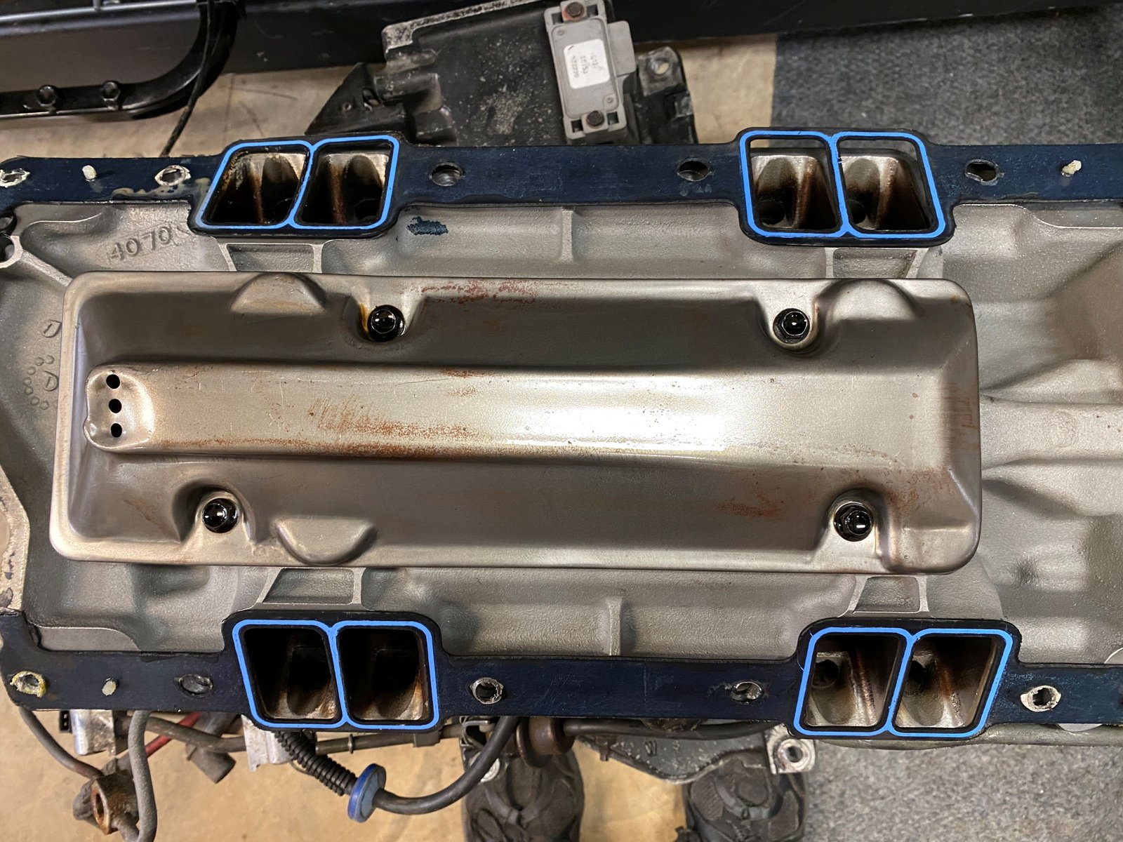
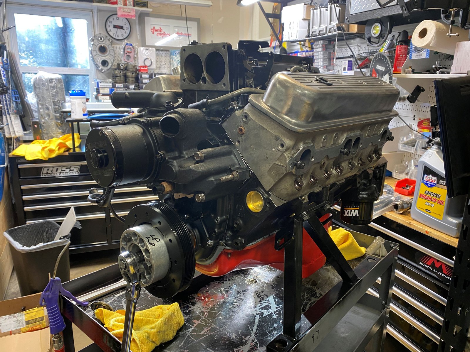
After dyno session: I'll be removing the dyno intake manifold
and installing the customer's LT1 manifold. Also cleaning up
the water pump and fuel rails and throttle body and installing those
items.
Just after removing the carburetor intake manifold. The
engine looks clean.
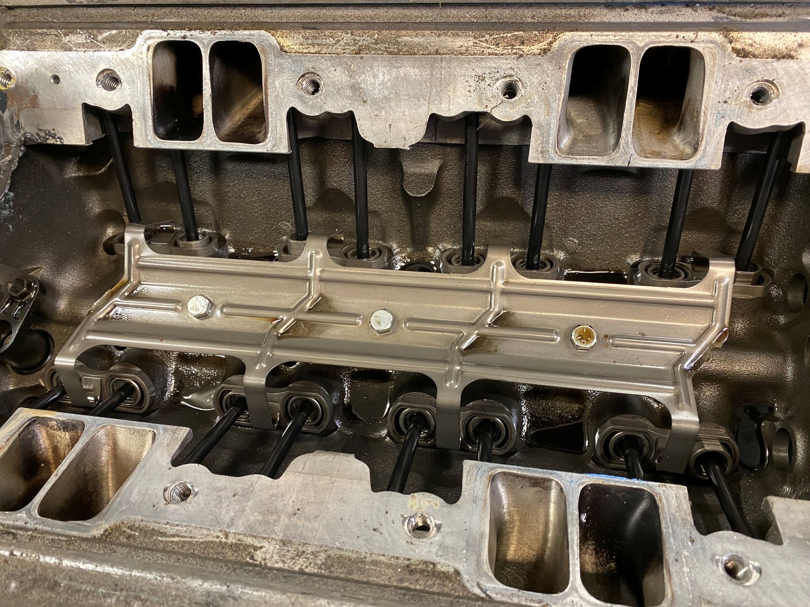
Not to forget the Tick Performance oil pump drive gear.
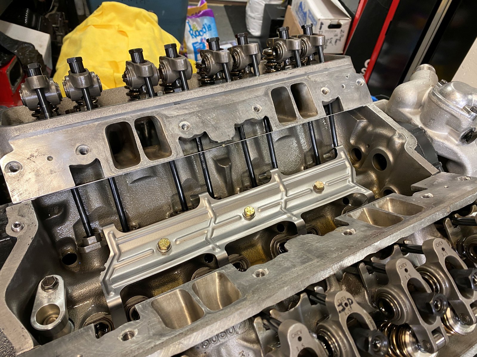
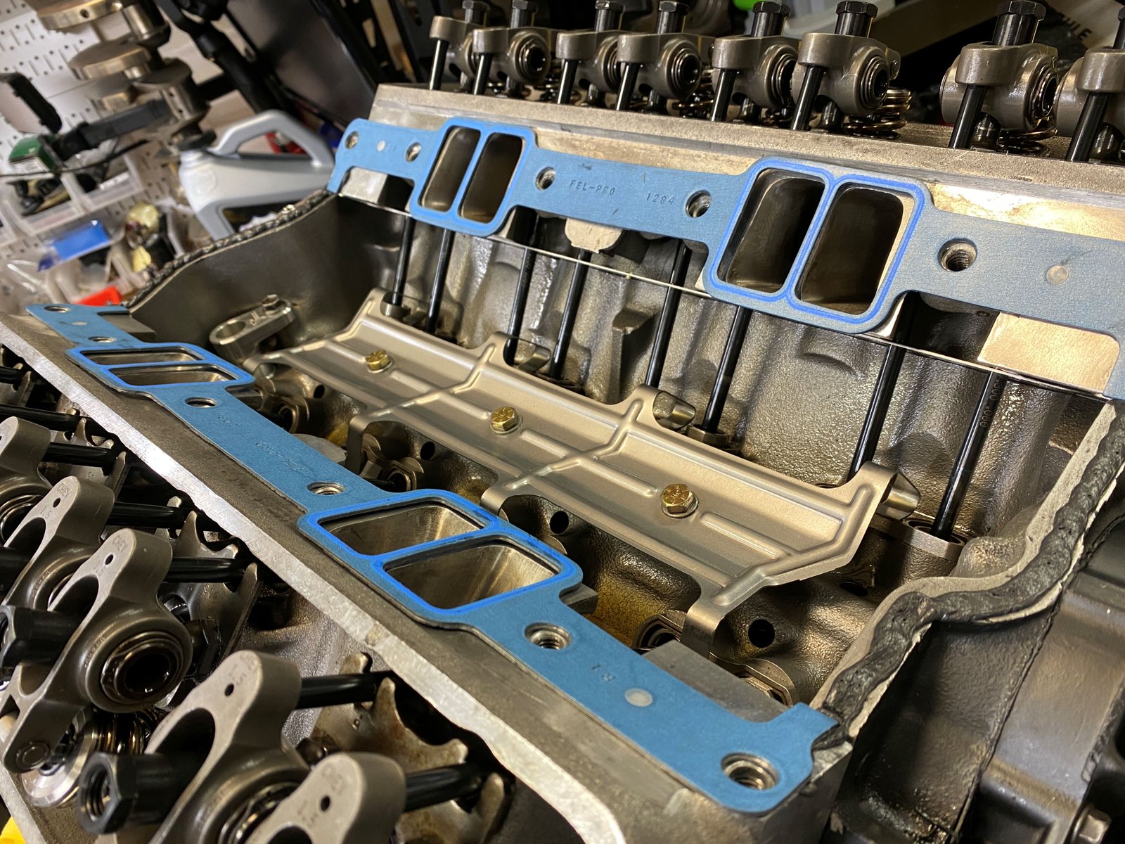
Now the intake valley is clean and ready for RTV.
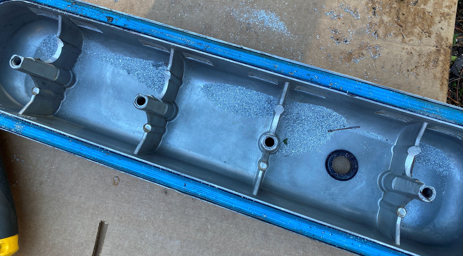
I did not use the customer supplied valve covers for the engine dyno
session because I could not get them to fit. I did not have
time prior to the dyno to figure out why so I used my own pair of
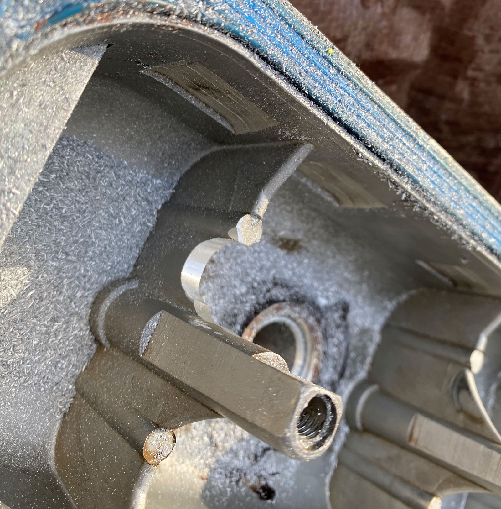
valve covers. This is where the rockers rub on the valve
covers.
Clearance that area and clean the aluminum chips.
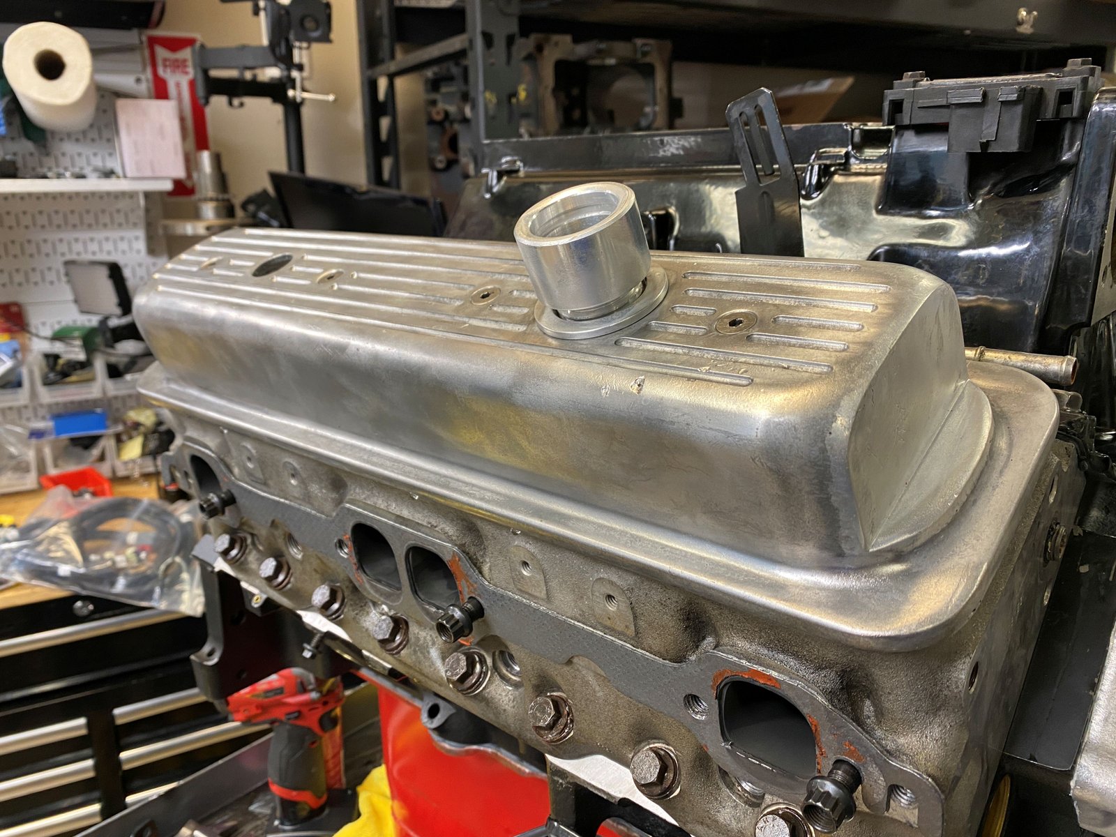
Fits nicely.
This is the driver's side valve cover.
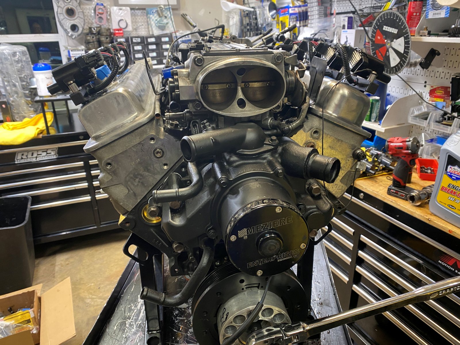
Notice the flat black water pump. The pump was cleaned and
painted and I'd say it looks pretty good.
I tackled the fuel rail cleaning and then installed the
freshly cleaned and flowed fuel injectors. They are 60 lb/hr
Siemens Deka high impedance injectors. They actually flow 64
lb/hr..