|
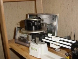
Weight of piston, pin, locks, rings = 720g
This piston has a 26.5cc dish with quench pad.
|

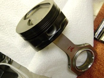
Very hard to take a photo of a
black piston.
The piston posing here has gas ports and the one used in this motor
does not. Notice that the 1st ring is far away from the piston top.
That allows for less heat on the rings. You can gap the rings
to almost natural specs.
|
|
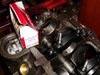
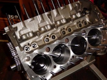
10-26-07: Ai will be shipping the TFS heads next week. I
need to get busy on the short block. Cam bearings shown here
are the performance coated version. I have a lot of these on
the shelf so here is a free upgrade to the customer.
|
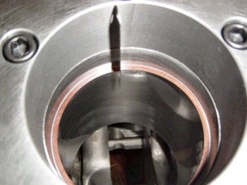
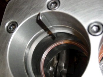
This is the rear most cam bearing. (Oil hole at 12 o'clock).
|
|
Front cam bearing oil holes align to the 1 and 5 o'clock
position. Also see the threaded oil galley plugs.
|
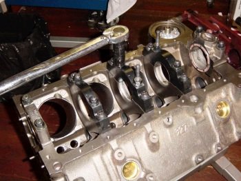
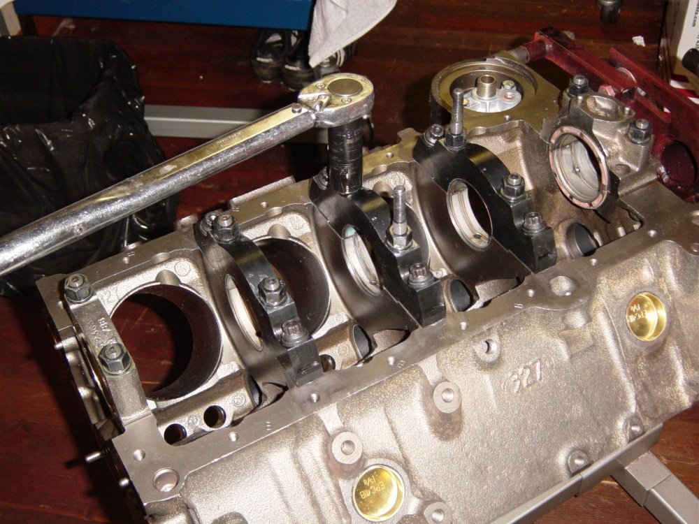
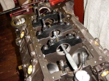
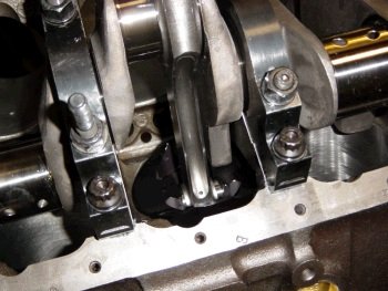
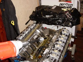
Now to the mains. Standard size Clevite "H" bearings
installed and Callies caps torqued to spec. The 3 tall studs
are Milodon and the rest of the hardware is ARP.
|
|
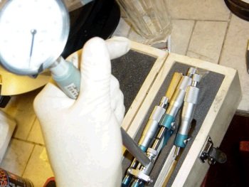
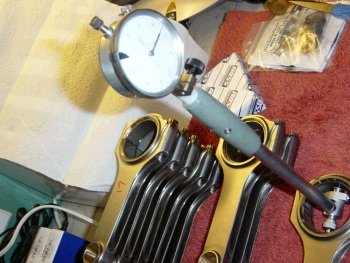
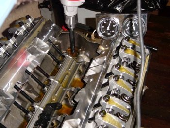
One way to measure main bearing clearance is to measure the crank
main journal (2.4490) and set the bore gauge to "zero".
|
Gauge pose photo:
With the gauge at zero just probe the mains and see how far off zero
they are.
|
|

#4 is a bit too tight, (.0015") so I'll purchase a set of X
size bearings. X size bearings are made oversized for extra
clearance.
|
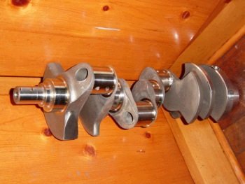
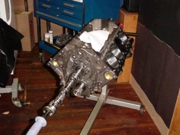
Here is the Compstar/Callies 3.750" stroke crankshaft.
Balanced to 1849g bob-weight at the Callies factory. Checked
locally to be right-on 1849g.
|
|
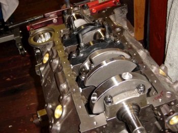
Crank is installed just as a test fit. (fits very nice and spins
freely). I don't want to go too far with this until I get the
new bearing set.
|

Nice close up of the Compstar crank.
Next step is to file the piston rings, assemble rods/pistons,
install rods/pistons, verify clearance of rods to block and piston
to crank.
|
|
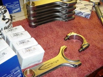
The Compstar 5.850" being cleaned and measured for bearing
clearance. All of the rods received standard size at top
and .001" at the cap.
|
See that rod with the 17 written on it? It eventually ended up
at .0022". All rods came out to .0022 to .0025"
bearing clearance using Clevite H series narrow.
|
|
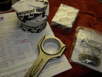
I want to get a rod and piston assembled and installed to check for
piston deck height and potential problems with clearance. The
piston and rod are laying on the Ross custom spec. sheet.
|
Assembled with 2 spiro-locks per side.
|
|
Installed with no rings but with the oil ring support rail.
|
Measured to be right at zero. Nice to go as planned. The
ROSS piston is usually built with .008" more compression height
than other pistons. My blocks are not zero decked but are at
about 9.005 to 9.010" and that works out nicely for all piston
types. It allows me to ask for more piston crown thickness.
|
|
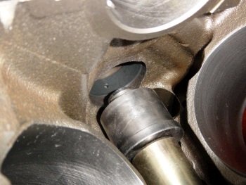
My mistake. I did not specify a short rod crankshaft from
Callies.
|
The piston bumps into the crank counterweight at bottom dead center.
Turns out that doofus me ordered a 6" rod cammed crank and we
have 5.85" rods here.
|
|
Ordered new crank from Callies
today, (cammed for 5.85" rod). Continuing on with the motor
here is the torque plate installed prior to file fitting the piston
rings. I don't think the plate is needed for ring filing but
since I have it I might as well use it.
|
Top ring at .020".
It is a chromesteel 1.2mm ring from Total Seal.
|
|
2nd ring is filed to
.024". It is a ductle iron 1.2mm from Total Seal.
|

Filed rings stored in their
cylinder bores.
|
|
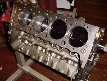
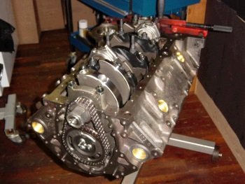
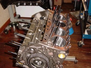
New crankshaft arrived and I got busy and installed the
rods/pistons.
|

The new crank had good piston
to counterweight clearance by the way.
|
|
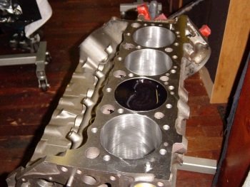
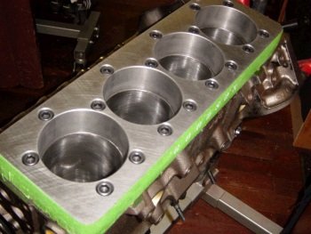
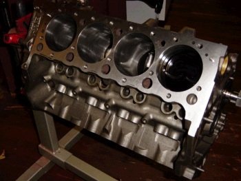
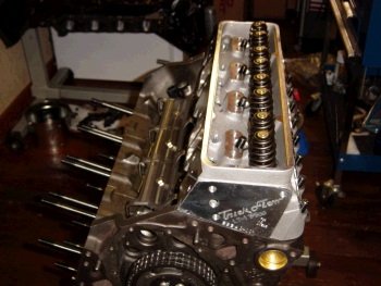
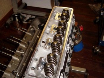
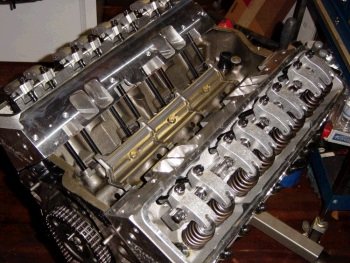
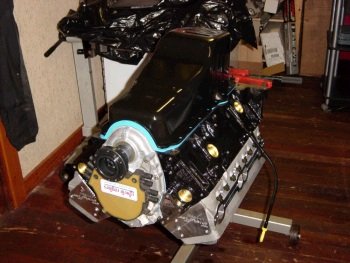
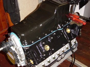
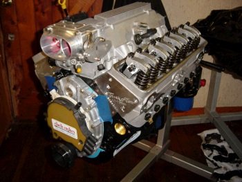
Assembled short block. The heads arrived from Ai last week
along with the rest of the valve train, (except for the camshaft).
This is about as far as I'm going until after the Thanksgiving
holiday.
|
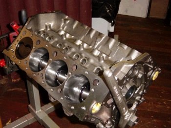
I checked all areas of the
rotating assembly for block clearance. Now I need the cam and
timing set to make sure that the rods clear the cam. I want to
do that before I put the Ai heads on just in case I need to
disassemble everything again.
|
|
Cam arrived. This is a custom grind from Ai on a billet core
with Everwear gear. I'd
like to show a photo of my cam degree set up but my digi camera
would not turn on. The Cloyes crank sprocket is set at
"zero". The cam came in at 105.5 deg intake lobe
centerline and the cam card specified 106.
|
With the cam installed I
listened and looked carefully for rod-cam interference. All
good.
|
|
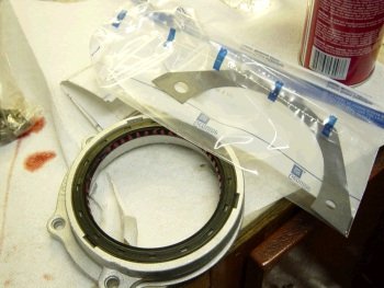
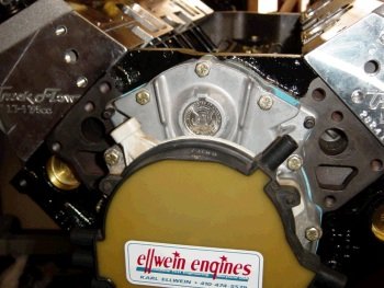
My camera cam back to life. I think the on-off switch is
dirty. I'm showing the new GM rear main seal housing in this
photo.
|
All ERE short blocks and long
blocks receive this new GM rear main seal and housing.
|
|

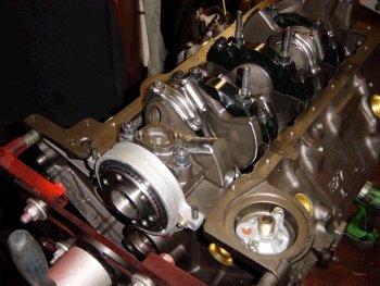
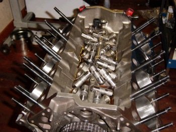
Going forward now to install the Ai TFS heads and install Jesel
shaft rockers and measure for pushrod length. ARP head studs
receive thorough cleaning and then Right Stuff RTV on threads.
|
The other side.
|
|
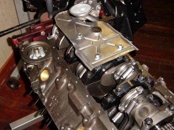
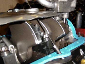
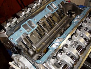
Oops. Before I show the heads, here is the M99HVS oil pump and
stock windage tray. The tray gets bent a little to clear the
rods and cut to clear the oil pump. Leaving the oil pan off
right now.
|
Muli-Layer-Steel head gasket.
|
|
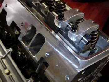
Ai 215cc fully CNC ported TFS heads. 62cc chamber.
|

Another view.
|
|
Installing Jesel shaft system. Top 4 head studs swap to Jesel
supplied low head profile bolts.
|
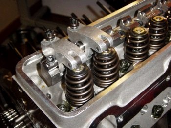
Jesel shaft stand installed, (no shims). One pair of rockers
and an adjustable pushrod.
|
|
Forgot to show the lifters. These are the GMPP LS7 #88958689.
|
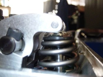
Pushrod length check. Ideal should be 1 turn in on the Jesel
pushrod adjust nut. The pushrod length here is 6.875 so I'll
order up a set of CV products 3/8" 6.850". (Ai supplies
these for me)
|
|
Two more photos of the Jesels. These are out of focus. Sorry.
|
My camera "macro" is getting hard to focus.
|
|
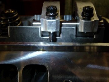
Test fit of Canton valve.
|
Sanded down on the shaft bolt.
|
|
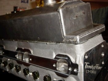
That was quick and easy.
|

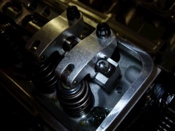
Was not 100% happy with the rocker tip to valve tip location, (a bit
too inboard). Right head gets a .050" shaft shim and the
left head gets a .030" shim. Now my 6.850" pushrods
are almost too short. I have a set of 6.950" on
order from Ai, via CV Products but they have not arrived. I do
want to pre-lube the motor so I'll put the 6.850" pushrods in
for now..
|
|
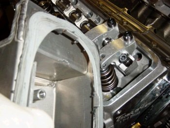
Now doing all the last minute details. Today's goal will be to
install the oil pan and let the RTV set up for a day so I can add
oil and pre-lube the motor. I turned the crank with all the
valve train fully installed and adjusted and it takes 30ft-lb to
turn the crank.
|

Here is another view of the sweet and high quality valve train.
|
|
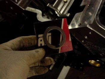
Before I put the ATI (F-body) hub on let's not forget to install the
reluctor spacer.
|
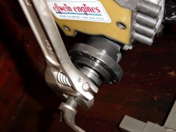
The F-body hub is the shortest of all in the LT1 family. A
conventional hub install tool works well with little
modification. The Y-body and B-body hubs are so long that most
tools just don't reach.
|
|
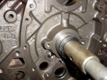
Kennedy half dollar plugs the water pump shaft hole.
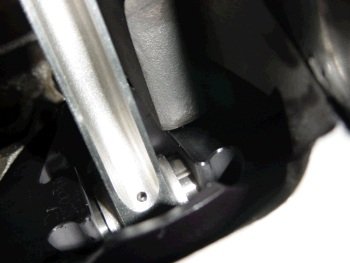
|
One last out-of-focus view of the dip stick which must slide past
the Callies main cap. The stick will probably wipe one side of
the stick dry of oil when removing so make sure to keep that in mind
when checking oil level.
|
|
Before installing the oil pan I made sure the oil pump pickup is the
correct height and also checked for any connecting rod
interference. No rods hit the pan but I pounded out the usual
area for rods #1&2.
|
Pan torqued in place and RTV needs to dry for a while. Turning
the rotating assembly sounds good, no bumps.
|
|
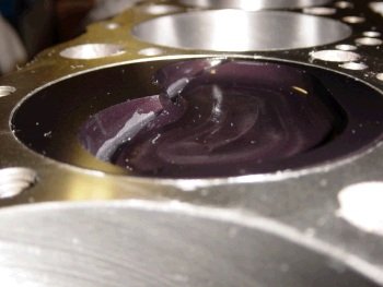
Now it's time to pre-lube the
engine. Oil pan is on, crank damper is on, rear cam-plug in,
oil galley taps plugged, filled with 4.5 quarts of Mobil 1.
|
Heavy duty drill spinning a 2500rpm,
(5000rpm crank). It takes only a few moments for all the
lifters to fill with oil and up onto the rockers. Pressure
here is 60psig.
|
|
Intake manifold gaskets and RTV.
|
Power washed and degreased manifold.
|
|
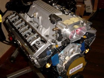
Another view.
|

And finally the 6.950" pushrods
arrived. Swapped them with the 6.850", readjusted lifter
pre-load and installed the ATI damper.
|
|
Re-usable shipping crate from Schribner
plastics.
|
Have a safe trip to Idaho.
|