|

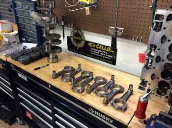
As with most short block projects the collection of parts is the
fist step in the build. Today I received the Callies Ultra
I-beam rods, (USA Timken).
|

Placing everything on both scales, the 3-beam lab scale and my
cheap digital mini. The piston is a new part that I've been
using for the past year with 1mm piston rings. (you won't find
it in Summit Racing).
|
|

King HPN rod bearings. The best that money can buy.
|

This is a total weight check of piston/pin/locks/rings
combined. Here the scale shows 562.3 and the individual total of
the same parts is 562.8, The bob weight is 1772g and Eagle
was called to balance the crankshaft to 1772g. (neutral).
|
|

While waiting for the block to arrive I'll measure and check a few
things.
|

Here are the GMLT1 heads which were CNC ported by Advanced
Induction. The heads were on the customer's previous motor and
just need a little cleaning.
|
|

Clean one on the left, dirty one on the right.
|

|
|

Chamber cc verification. This photo is at 52cc, 2 more ml
makes it 54cc, (give or take 1 cc)
|

Heads cleaned up as well as my equipment can clean. I
calculated static compression ratio for the motor to be 12.26:1
assuming the pistons will be .010" in the hole and using the
.039" FelPro 1074 head gasket.
|
|

|

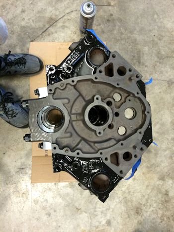
Aug. 10th, 2016 Update: Fully
machined block arrived via tractor-trailer from New Hampshire's Chad
Golen.
|
|
|
Block has been buffed to remove casting
flash and a few other things, (I'll show later). Here is the 1st
application of the POR15 engine paint. I lay it on pretty thick.
|
|
Now measuring crank/rod bearing clearance.
|

Callies Ultra 6.0" rods
|
|

Mahle piston part numbers. I don't know what some of the
numbers mean but maybe it will be good info in the future.
|

Eagle rod journals are all at 2.0990"
|
|

Here is my rod bearing clearance set up.
|

Torqued to 83ft-lb on my wrench to give .006" stretch.
|
|

King bearings (standard size) give .0025" on all except #5
which is .0024"
|

|
|

|
Waiting for the block paint to dry......
|
|

Cam bearings installed.
|

Notice the oil gallery threaded holes.
|
|

Another view of the cam bearings.
|

Time to measure for main bearing clearance.
|
|

|

.003" at the rear main and from .0018" to .0021" on
the other mains. Using King premium main bearings in all
positions except #1 (the front main). #1 is using Clevite P
series due to the softer cap.
|
|

Installing camshaft, (Advanced Induction).
|

|
|

Now the crankshaft, (Thrust is at .008)
|

|
|

Piston at .000" deck. (I normally desire it to be a bit in
the hole but this is ok).
|

Cam degree check. 104 Intake Centerline.
|
|
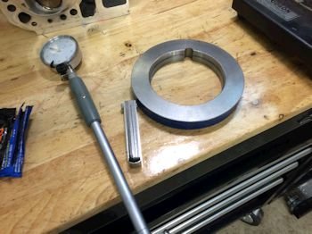
Here is where I measure the bore size (simply for the blueprint
records). Here is my bore 4.030" bore gauge.
|

Now transferred to the bores. All checked to be 4.030"
Sometimes I have the bore taken to 4.031" but that is for race
motors.
|
|

Now filing the rings to .020" top and .020" 2nd.
|

|
|

Verified at .020". Piston is still installed from when
I checked deck height and cam degree.
|

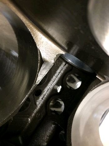
Minor delay found while installing rods/pistons. The rods
bump slightly at the inboard side, (the cam side), of the bore
bottom. I had to disassembled the motor and grind clearance and
re-washed.
|
|

For my records: Photo proof that I installed the rear main
cap oil galley plug. The photo to the right is where I
clearanced at the bottom of the bore for rod clearance.
|
|
|

After grinding, cleaning and reassembly I degreed the camshaft one
more time just to make sure all is lined up properly. This time
I got 105 ICL.
|

All rods/pistons installed and rod bolts torqued to 80ft-lb.
.020" rod side clearance.
|
|

|

From timing cover ARP stainless bolts at 15ft-lb.
|
|

|

Modifications to the windage tray and the Lokar dip stick tube.
|
|

The old oil pump is a M55HV.
|

Standard gears on left, HV gears on right.
|
|

I swapped the pump out for a standard volume. The pickup
gives too much clearance, (5/16").
|

Swapped it out for another pickup that I had in my stock
drawer...now at 3/16" clearance.
|
|

|

|
|

Canton oil pan all cleaned out. The windage scraper won't be
here for long.
|

Here is a view of the stock windage tray and my
modifications. I make the dip stick hole bigger and I bend it at
the edges to fit the oil pan.
|
|

The pan scraper hits the main caps. I removed the scraper
and cleaned the pan.
|

Now she fits well.
|
|

|

|
|

|

|
|

Lifters installed.
|

|
|

Cometic .060" thick head gasket.
The photo to the right is out of focus but I tried to show the area of
the block that I ground down to allow for oil to pass through the
gasket opening and into the intake valley. The Cometic gasket is
not cut properly in this area.
|
|
|

|

ARP head bolts cleaned and thread sealant applied. Also
applied ARP lube to the head and washer area.
|
|

|

|
|

|

Rocker cleaned and ready for installation.
|
|

7.2" pushrods fit quite well. Rockers installed at
3/4" turn past zero lash.
|

|
|

|

|
|

Ready for the dyno
|

|
|

Here I am creating timing marks for the stock pulley/damper.
I located and marked top dead center using the piston stop method and
then matched the marks from an identical diameter damper that already
had timing marks. This is essential for the dyno testing.
We need to know where timing is because we use a standard distributor
with a carburetor.
|

Here is the oil pressure test along with hydraulic
lifter/pushrod/rocker oil check. This drill spins the Melling
10552 oil pump to 62 psig.
|
|

|

Here is the motor in dyno trim at Morgan International, (the day
before testing).
|