|
|
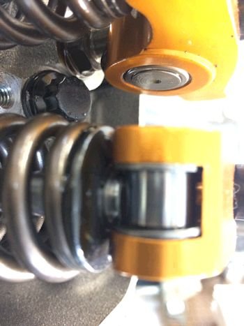
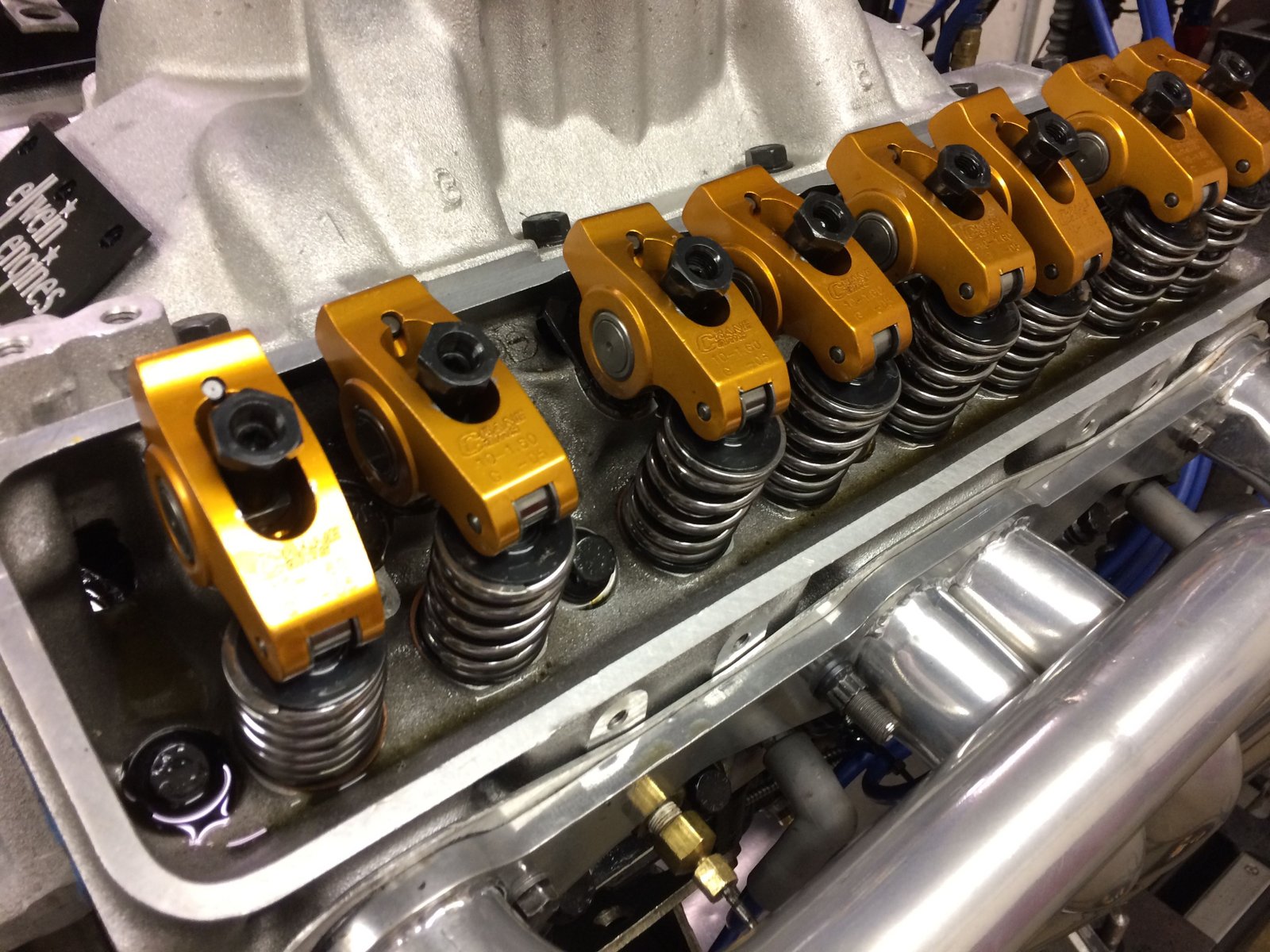
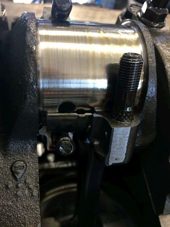
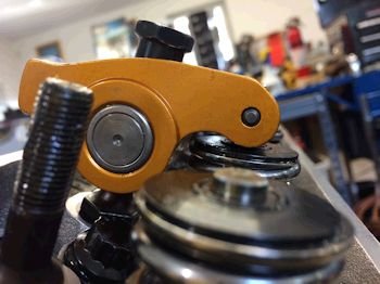
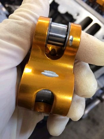
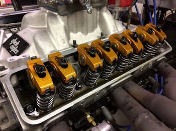
The self-aligning rockers need a lot of valve tip in order to keep
from hitting the retainer or keeper. This looks ok but very
close to hitting.
|
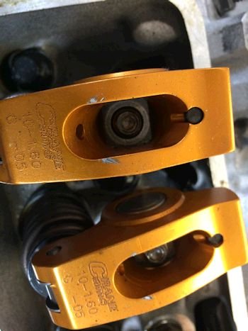
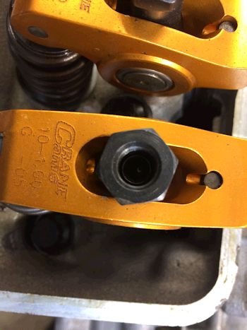
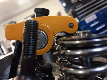
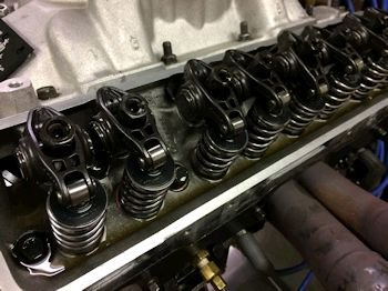
The rocker poly-lock nut slightly rubbed each rocker but eventually
clearanced itself. This is pretty common and again no
harm-no-foul.
|
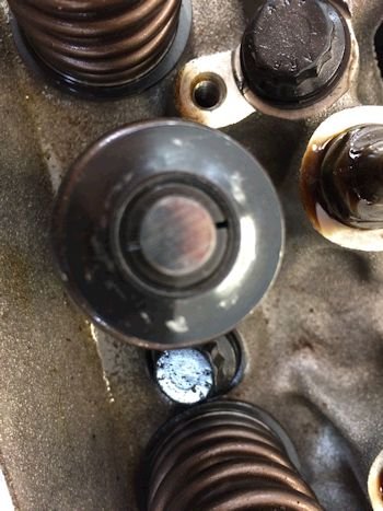
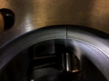
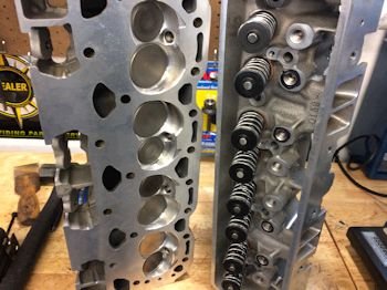
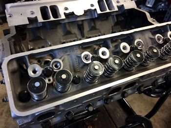
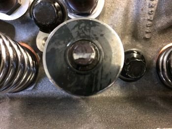
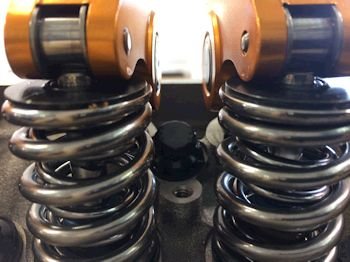
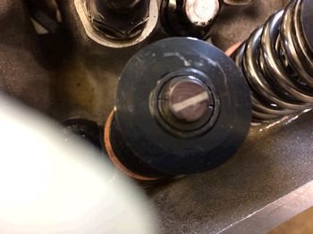
Each valve retainer had slight witness marks from hitting the rockers,
(probably happened at high rpm). This would cause the rattle
sound. Nothing is broken or overly worn but I'm sure eventually
a rocker would have fallen off the stud or a spring would have broken.
|

|

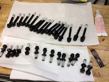
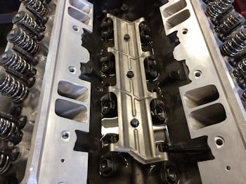
There is a bit of fine metal pooled in the lifter valley that probably
came from the rockers and valve retainers. All of the lifters
looked good visually except #1 intake lifter was difficult to remove
from the lifter bore. Some valve float pounding?
|
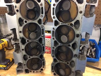
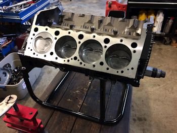
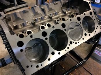
The combustion chambers look excellent!!
|

Pistons and bores look good too. No oil burning.
|
|
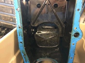
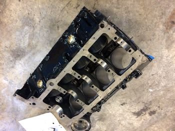
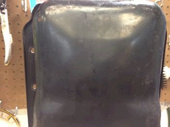
The oil pan looks great! No debris what-so-ever.
|
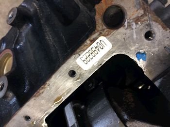
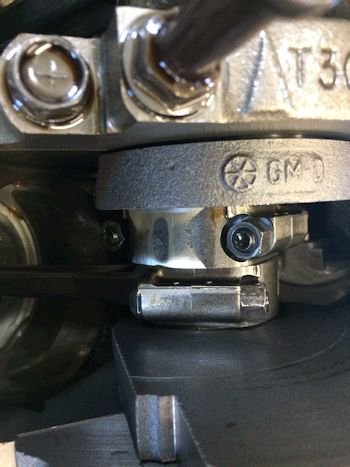
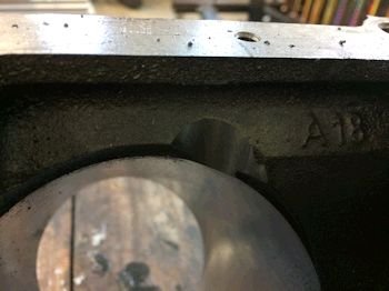
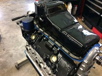
I don't know this label but it's probably GMPP replacement 4-bolt
block lingo.
|

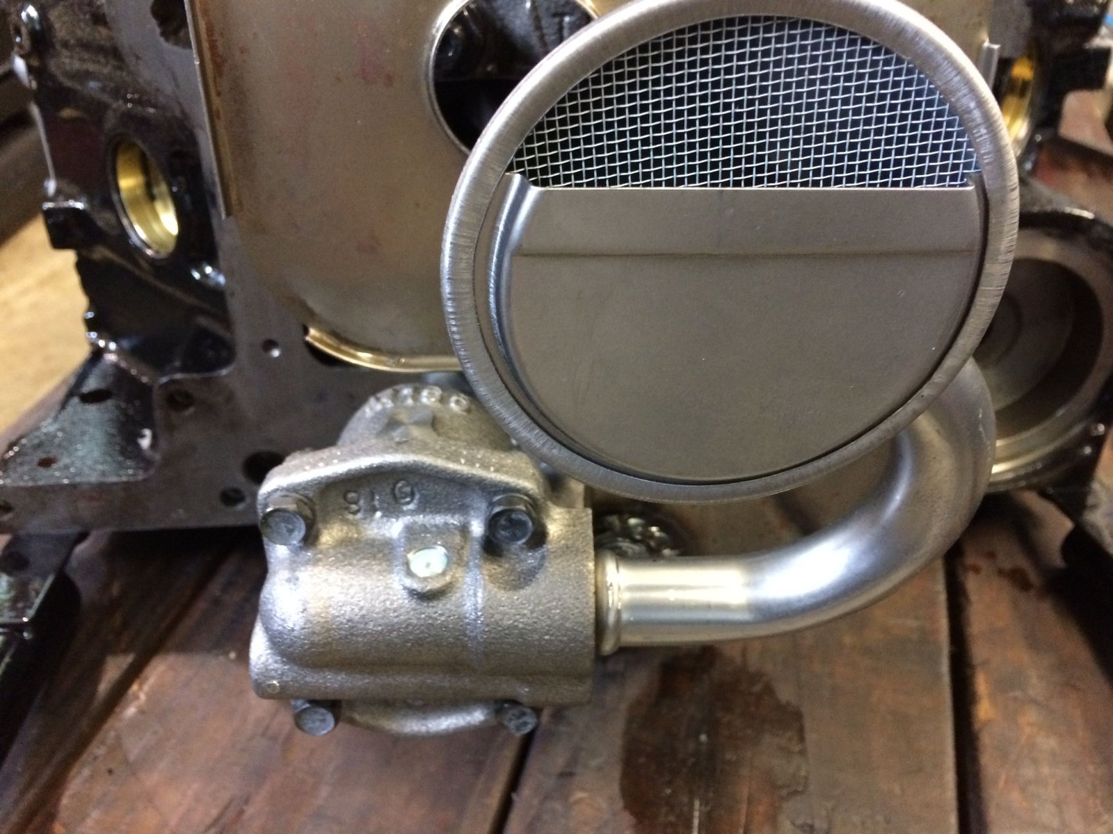
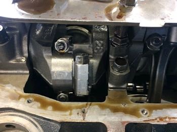
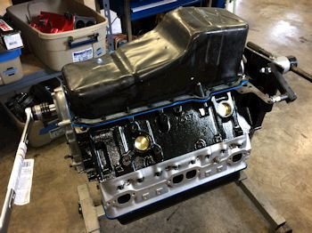
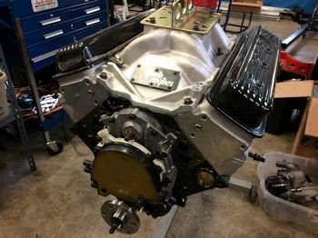
This would not be from the factory...the HV oil pump.
|
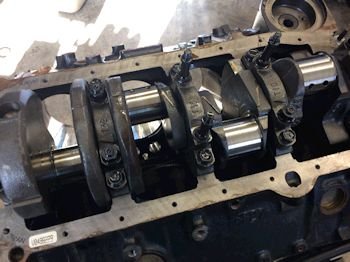
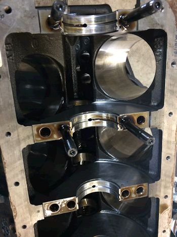
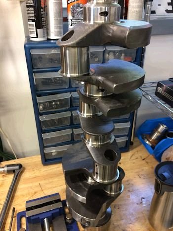
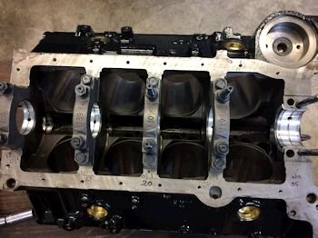
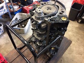
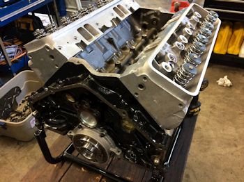
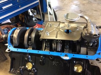
It's a very nice bottom end.
|
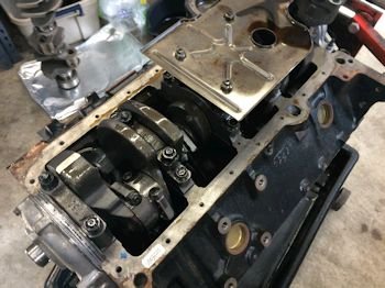
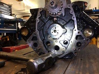
I'm happy to see the builder has the windage tray installed. The
HV oil pump is prone to cavitation but the windage tray will certainly
minimize the risk.
|
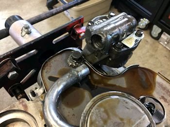
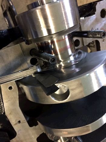
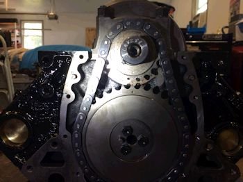
The pump had the 3/4" pickup RTV'ed in place and you could easily
move it and pull it out. But the system worked. The bottom
end looks to be in good shape. The pickup stayed in place until
I pulled it. I have installed pickups like this in the past but
with 3M boat calking.
|
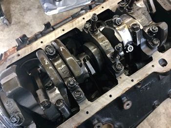
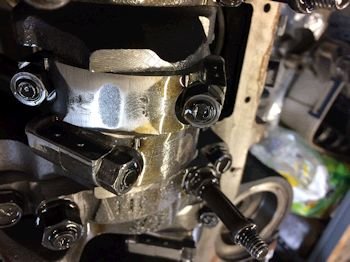
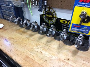
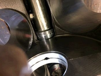
Nice 4-bolt mains. Rods were balanced by evidence of the buffing
on the lower cap.
|
|
Next on the to-do list is to get the block
to the machine shop and order a 383 rotating assembly.
|
|
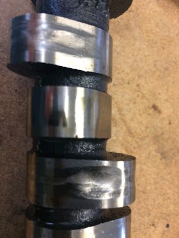
Upon further tear-down and inspection we find #1 intake and
exhaust cam lobe wiped. That is the cause of all the fine
debris. The lifters were ok. Maybe a soft cam core?
|
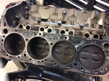
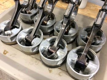
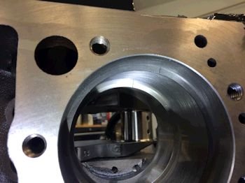
Oh boy! I've never seen this before. The builder
installed all of the right side pistons/rods backward. #2,4,6,8
were facing forward. The piston dots were facing rearward.
But this error did not seem to cause any damage. The pistons and
rods looked great. The cylinder bores looked great. The
only problem I can detect with the running of this motor was possible
valve float at high rpm and the cam lobe damage.
|
|
|
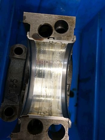
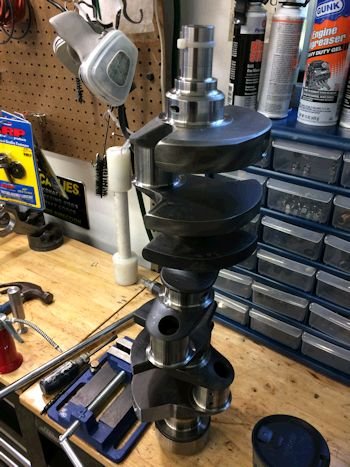
The crankshaft does not spin freely. The main bearings must
be gummed up or tight. Upon removing the crankshaft it looks as
though the main bearings are scratched up with dirt, (from the cam
lobe wipe).
|
|
|
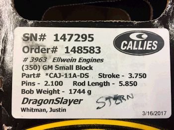
Project moves into the parts combo phase:
Callies 1-piece rear main seal
Dragonslayer crankshaft.
Callies 6" Compstar H-beam rods.
Mahle premium D-Dish piston with 1.5mm
rings.
Callies has 4 crankshaft on the shelf
assigned to me. Now it's time to call for one and have it
balanced. (1744g).
|
|
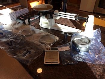
I use a pro 3-beam scale and a
cheap flea-market digital.
|

The Mahle SBC125030I16
|
This scale is used as a 2nd
check. It's 1 gram high.
|
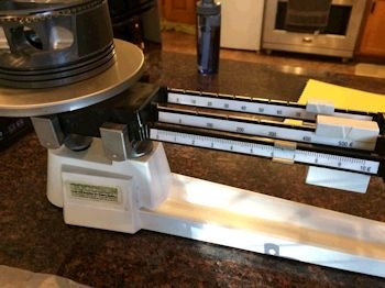
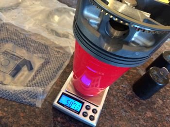
After weighing all parts
individually I weigh the piston/pin/lock/rings all as one and make
sure it matches the sum of the individual parts.
Piston 432.0g, Locs 2.2g, pin 117.0g, rings 35.0g = 586.2g...then rods
450/174g, King bearings 39.0g. (6g for oil) = 1744g
|
|
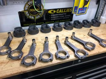
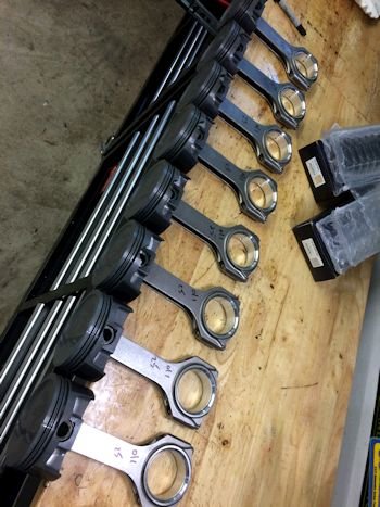
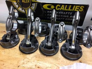
The block is still at the machine shop but I'll get the pistons
and rods mated up in the mean-time.
|
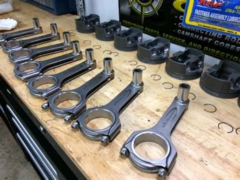
Callies/Compstar 6" H-beam rods.
|
|
Mahle -16cc D-dish piston #SBC125030I16
|
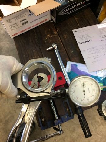
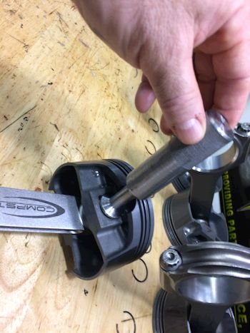
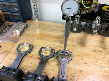
Checking rod bearing clearance I start with torquing up the rod,
(.005" stretch or 80ft-lb).
|
The Callies Dragonslayer crankshaft rod journals mic out at
2.0990".
|
|
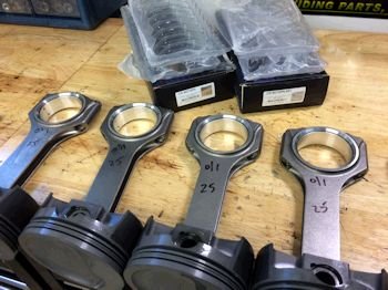
King rod bearings installed. The 1st rod to the left was
using standard size on top and bottom which gave .003"
clearance. Then after mixing .001" and standard it came out
to .0025". That is more like it. All 8 rods then received
standard size for the top and a .001" under for the bottom.
All came out to .0025" clearance.
|
|
|
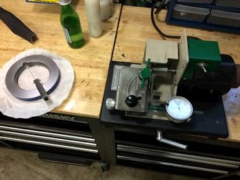
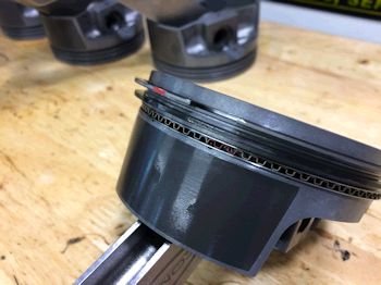
Now file fitting the Mahle piston rings.
|
The target it .019" 1st ring and .016" 2nd ring.
|

|
|
|
Stay tuned. The block should be
finished soon and the assembly will begin.
|
|
|
|
Now the job is to clearance the bottom of
the cylinders for the stroke. I do this by hand and then mock up
a rod/piston combo and see if there needs to be more clearance.
Then POR15 black paint.
|
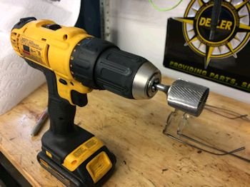
This is the drill bit used for block clearancing.
|
|
|
POR-15 Engine black
|
|

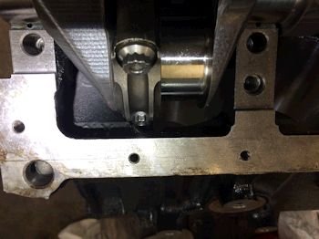
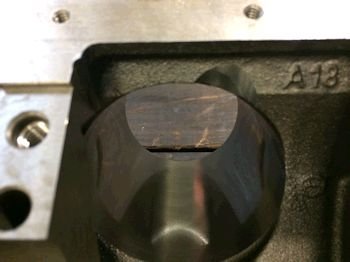
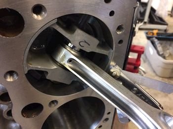
Here are good views of the rod clearance at the bottom of the
bore.
|
|
Now onward: Measuring for main cap bearing clearance.
King 557HP bearings and stock 4-bolt main caps to cradle and support a
Callies DragonSlayer crankshaft.
|
Most of the caps required a mix of .001" under and standard
size. The crankshaft main journal size mic'ed out to 2.478"
|

QC photo of the oil gallery steel ball plug in place.
|

|
Cam bearings being hammered into place.
|
|

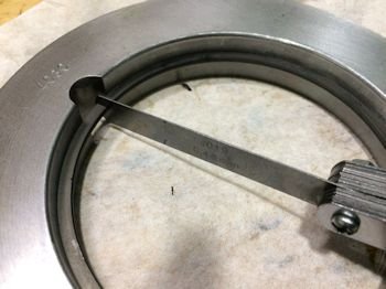
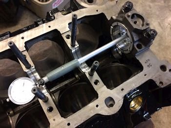
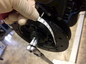
Main thrust bearing feeler gauge at .004" and then total
crankshaft endplay at .007" with the rear main cap torqued to
spec.
|
|

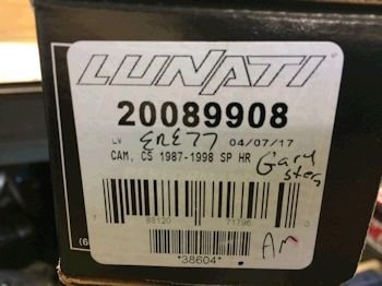
Lunati camshaft from Lloyd Elliott.
|
Stock weep-hole oil galley plugs installed for cooling of the
timing set.
|
This is a GM extreme timing set, (being re-used).
|
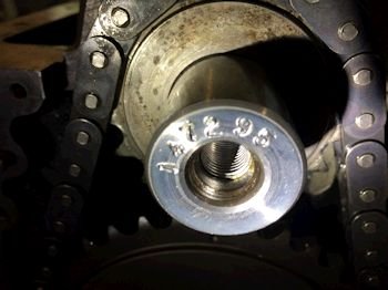
Serial number of the Callies crankshaft = 147295
|

|
|
Double check of the ring gap in the actual bore as opposed to the
bore gauge tool.
|
|
Here is how I check piston to bore clearance. I use a feeler
gauge. A .003" fits and the .004" does not.
Mahle spec is .003 to .0035".
|

|
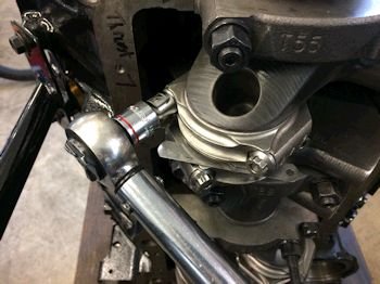
Photo to the left shows the pistons at.008" in the
hole. The block is not zero decked. I ask that it be
decked to about 9.010".
Photo above shows feeler gauge of
.018" (rod side clearance). All rod bolts torqued to
.005" stretch. (80ft-lb).
|
|
|

Camshaft degree check. Intake centerline is at 110* which
matches the cam-card.
|
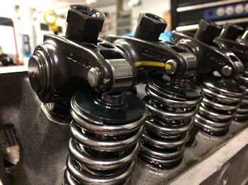
LE installed new valve springs.
|
|
|
|
New Comp rocker studs #45012-16. The self-aligning rocker passes
the check here. Good clearance between rocker and retainer.
|
|
And here is a pretty good witness mark of the rocker tip on the
valve tip.
|
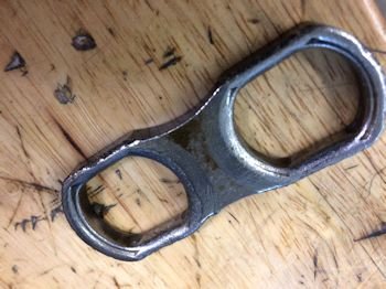
This was the lifter guide for #1 int./exh. I replaced it
with a take-off in good condition.
|
Crower 66330-16 hydraulic lifters and new spider.
|
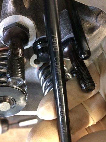
Reusing the Comp 7940 pushrod, (7.200")
|
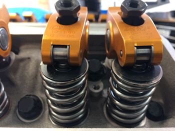
All of the rockers have these clearance/interference marks.
Right now it looks like there will be no clearance issues.
|
|
|
|

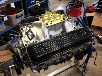
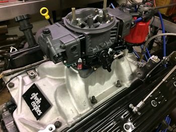
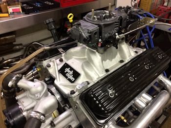
Getting ready for the engine dyno. GMPP dual-plane intake
manifold.
|
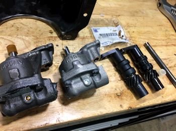
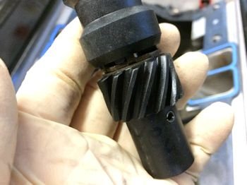
The previously used pump is the HV to the left. I'm
replacing it with a SV M155 but with a high pressure spring. The
refurbished oil pump drive gear is shown on the left and the old gear
on the right.
|
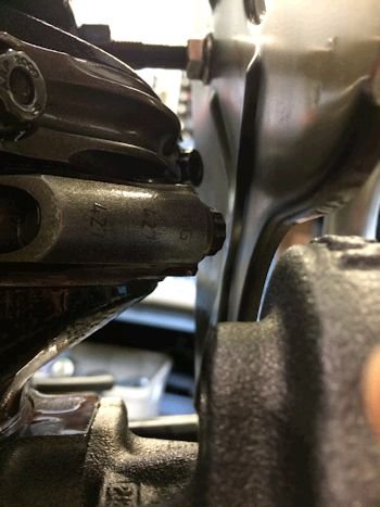
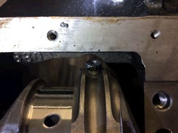
Rod-bolt clearance with the windage tray.
|
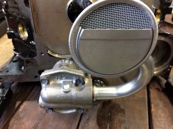
Stock 3/4" pickup installed by freezing and then pressing on.
|
|
Oil pan hammer message for #1/#2 rod clearance.
|
|
|
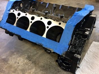
Oil pan on and painted.
|
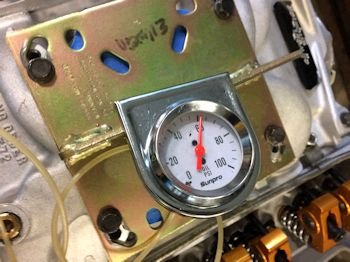
Oil pump and system pressure test: Cold oil @ 60psig with
rather low speed drill.
|
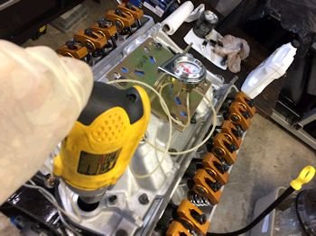
I spin for more than a few minutes until most of the rockers show
oil up from the pushrod.
|
Setting up for dyno: First I need to make sure my TDC is
accurate. The LT1 does not have an aftermarket pointer available
and so I make due with a gen 1 small block Chevy pointer from
ATI.
|
I use the piston stop method and it stops at 20deg BTDC and ? ATDC.
(no marks on damper after TDC).
|
And so I just find the 1/2 way point and it should be TDC on the
pointer/damper. Here is the tape I use which comes from my wife
Nancy's purse.
|
Then I set the distributor in place with #1 on the compression
stroke at about 36 deg. the fine adjust when on the dyno with the
timing light.
|
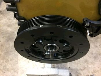
Look closely and you'll see "Neutral" written on the
rear main seal housing. I've installed the wrong flywheel at the
dyno and that is a pain in the butt to stop the session and swap to
the proper flywheel. This might help me reduce errors.
|
On the dyno at Jim Morgan Racing Engines [Morgan International]
|
|
Power falls flat at 5000rpm and above. Wondering if the
valve train is not up to snuff?
|
The next day: Swapped to 7/16" studs and
rockers....still flat above 5000rpm.
|
A few days later....new distributor, coil, ignition, Carb....still
flat. We will get to the bottom of this. Going to try new
valve springs and head back to the dyno.
|
Verification of pushrod length. Here is the trace from the
7.200" pushrod that has been being used in the engine and it is
more than perfect.
|
After buying a few tools, (it's about time I invested in cylinder
head tools)....I checked as found install height. It is
1.840" (that gave 140# spring pressure).
|

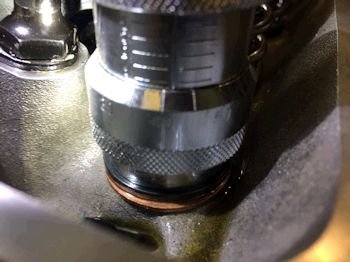
Here is my spring pressure checking tool. This is at
1.790" and that is 165psi.
|
|
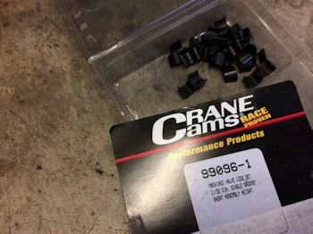
These keepers put the spring at 1.790"
|
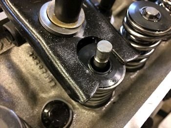
Here you can even see where to valve spring retainer was sitting
previous and the new height. The valve stem has a witness mark
from the old keepers.
|
|
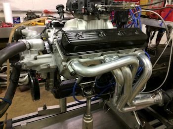
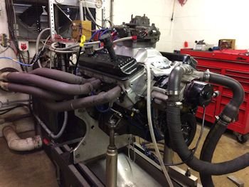
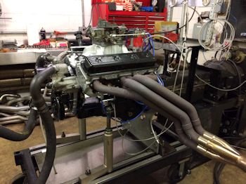
July 29th, 2017: Back to Morgan International Racing
Engines. Re-test ready. Notice my dyno headers.
Finally I came up with a set of my own headers and now I do not have
to use the circle track headers.
|

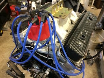
Here is my timing pointer system. I have a gutted optispark
which allows me to fit a traditional pointer. I set timing at
38* BTDC.
|
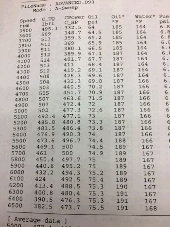
Such a smooth power pull. All is well.
|
|

|
The above pull was with the 7/16"
rocker set up. I swapped over to the original set up (3/8"
stud Crane rockers). Made one last pull on the dyno. Power
was 497@ 5700 and torque was 512 @ 4500 rpm.
|
There are a few more items to take care of prior to
shipping. The dyno oil needs to be drained and the oil pan
inspected, (all good). The carb manifold gets swapped out with
the stock LT1 manifold. The oil pump drive gear gets a new gear.
|
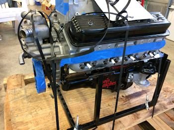
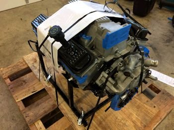
Engine bolted to a reinforced pallet.
|
|
I didn't think to take photos of the final
wrapping and the engine being placed on the truck. The engine
was wrapped with numerous layers of plastic wrap for a water resistant
package.
|