|

I begin by grinding for clearance at the cam tunnel area.
This is the area I hope will give clearance going by past
experience. The type of I-beam connecting rod that I'm using
will always need additional clearance in this area.. An H-beam
will not require additional grinding.
|

I decided to put the rear main cap oil galley plug in at this
time. I can always punch it out and install a new one if I end
up having to do more work on the block such as grinding and cleaning.
|

The main bearings are the King MB577XP and the oil hole does not
line up with the block. I decided to clearance the bearing instead
of grinding the block.
|
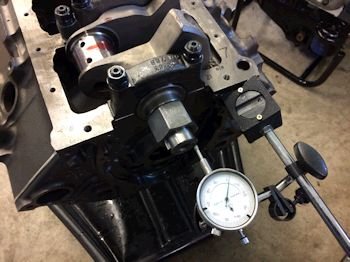
Main cap bearing clearance process begins. Here we have the
main thrust cap, (#5) at 0.0034"
|
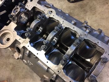
And the rest: All using standard size bearings top and
bottom. .0021 to .0034"
|

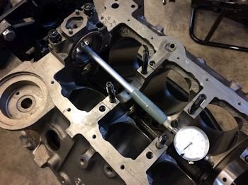
Main thrust by feeler is .004"
|
Main thrust after crank installed, (crank end-play) = .007"
|
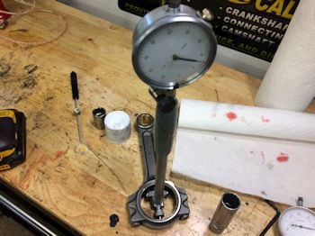
#1 Rod bearing clearance at .0026" (standard size King
bearings CR807XPN). All the rest were from .0026 to .0028"
|
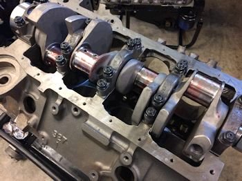
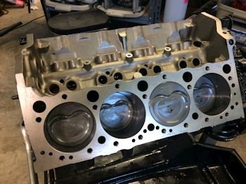
Time to see if the rods will clear the block.
|
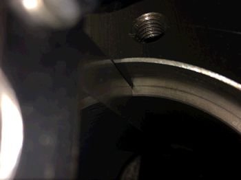
Right off the bat #1 rod shoulder bumps the inboard cylinder
bottom...(marked in yellow).
|

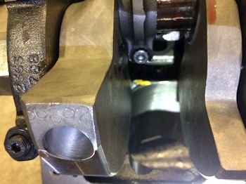
Here is a close up. I will need to remove the crank/rods and
grind in that area. On purpose I did not install the cam
bearings for just this situation. After all the block grinding
is complete then I will install the cam bearings.
|
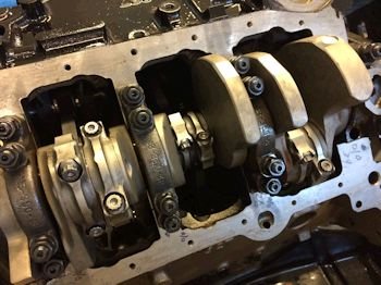
It turns out that all other rods clear. It was only #1 that
does not. That's not all too bad. Next on the to-do list
is to disassemble and grind/clean and reassemble.
|

More clearance grinding at the bottom of #1 bore.
|
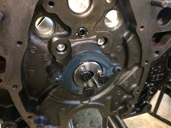
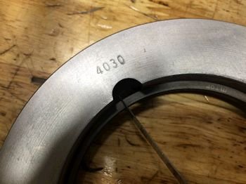
After a thorough cleaning of the block the camshaft bearings are
installed.
|

|
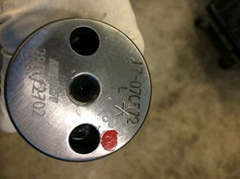
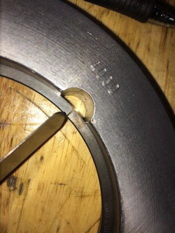
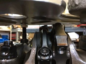
Here is a reference photo of the cam numbers. This is a mild
street cam grind #62801-62702-112, 215/227/112, .546"/.565"
with 1.6 rockers.
|
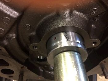
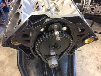
Camshaft installed. Oil galley plugs installed. These
have weep holes for oil cooling of the timing set.
|
Ring gap: Top ring at .018", 2nd ring at .014",
(Street/Strip all natural)...as per Mahle suggestion.
|
The ring gap is also checked with ring in the bore.
|
|
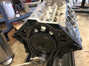
Timing set on. This is so that I can check each piston/rod
combo one at a time for clearance with the camshaft.
|

|
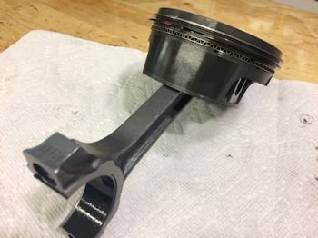
One final look at the rod/piston.
|
All installed and no interference with cam or block.
|

Rod side clearance is .020" to .022" Rod bolts at
70ft-lb
|

|
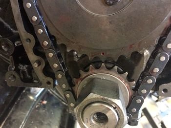
Crank sprocket installed at "O" (zero).
|
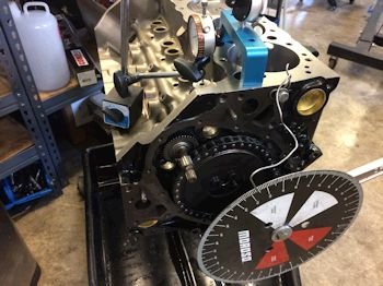
Intake centerline is dialing up at 106*. The cam card spec
is 108*.
|
Trying the +4 sprocket setting gives 102* ICL
|

Trying the -4 sprocket setting gives 110* ICL. I decided to
put it back to zero and go with 106* ICL.
|
|
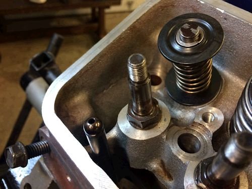
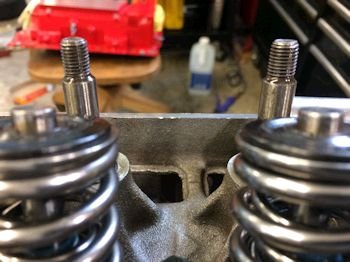
The heads are mostly bone stock genuine GM LT4. The owner
did a valve lap and new springs and seals. The non adjustable
rocker studs are shown in the photo. The pushrod length will
need to be established. In a nutshell the pushrod has to allow
for 1 turn past zero lifter pre-load.
|
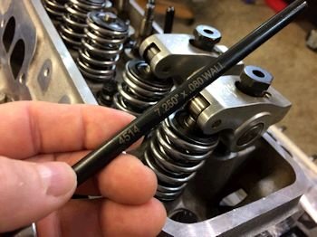
Turns out I have an adjustable pushrod and I set the pushrod
length that gave a tight rocker nut at 1 turn past zero
pre-load. That ended up being 7.310", (Stock is 7.200"
and so I'll order a set of 7.300" pushrods).
|
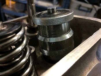
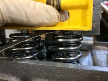
I also want to check the valve spring height with various
keepers/locks. This shows 1.748" with the locks in the
Lunati spring kit.
|
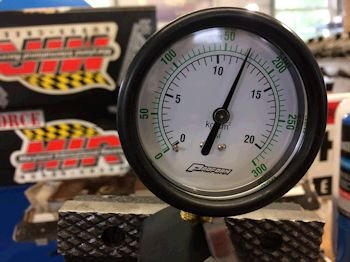
In the vice a 1.748 compressed spring gives 170psi. I like
it.
|

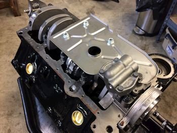
Back to the bottom end. I have a re-supply of Milodon
windage studs and have them installed.
|

The stock windage tray is massaged up and away from the rods.
|
|
Melling M155 oil pump.
|
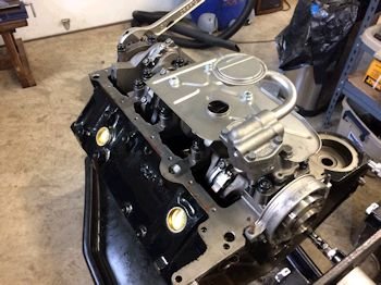
Now with the oil pump pickup.
|
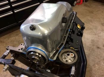
Now the Corvette oil pan. Surprisingly it did not need to be
massaged for rod clearance.
|

|
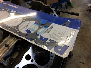
FelPro 1074 head gaskets. .039" - .003" =
.036" piston to head clearance.
|

|
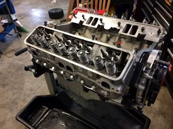
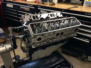
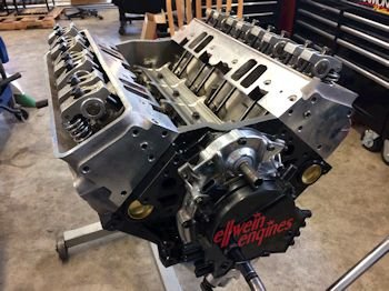
Heads on with ARP head bolts at 70ft-lb
|
|
Back to the valve spring and making sure they are mostly all the
same spring height. Since there were no shims installed, (just
spring locators), I want to make sure all of the springs are similar
in height. Some valves are showing less tip than the others
indicating the spring would be installed higher, (1.760").
I checked all that were "off" and installed Crane locks
which brought all of the springs in the range of 7.740" give or
take .005"
|
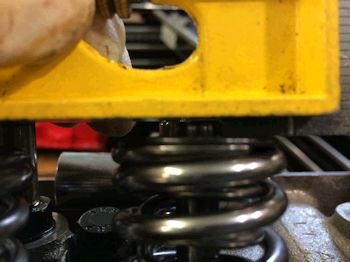
Here is a visual of the shorter valve tip.
|
The one on the left is the 1.740" spring and the one on the
right is 1.760"
|

Swapping valve locks.
|
Back to the pushrods. Turns out the 7.300" pushrod was
too long. Thankfully I had a set of 7.250" by TREND.
|

All rockers are from 3/4 to 1 turn after zero pre-load. The
preload is not adjustable. The 7.250" pushrod allows for
the 1 turn after zero pre-load (tight rocker nut bottomed out on the
rocker stud).
|
|

|
|