ERE-395 #92
4-Bolt Splayed cap 395 short block Nitrous F-body.
Callies Ultra Rods, Diamond custom pistons, Callies crankshaft.
Here is the core. This has a
ProGram main cap for center 3 and the front and rear. Took
about 1 year to receive these.
Block returned from 4-bolt main cap installation and
bore/hone/decking procedure. I still need to do quite a bit
of prep work on the block. I'll grind and buff off sharp
edges and clearance the bottom of the cylinders for the extra
stroke, (rod clearance), and thread tap the front oil gallies, and
clean and paint.
Here she is after grinding and buffing. I do all of this
work outside (even if it's cold outside). I brought the block
back inside to do the oil galley thread tapping, (photo not taken).
The outside of the block is smoothed basically to help it look
better after the paint job.
Looks like I've already cleaned the block with my hot water
pressure washer and scrub brushes. It also gets blown off with
compressed air and oiled with WD40 and wiped with micro-fiber cloth,
(less lint).
You should be able to see the clearanced area at the bottom of
each cylinder.
I've been making an oil drain back path for every block at the
left front. Most head gaskets do not block this spot but the
MLS Cometic gasket blocks off in this area.
Painted outside too. Brought inside to warm and dry.
I mask with a used MLS Cometic head gasket and old timing cover
and rear main seal housing. The paint on the deck surface is
on purpose. That will help prevent rust when the engine is in
the car.
Now every engine is painted with Eastwood 2 part ceramic
catalyzed urethane. $24/can. It's as strong as POR15 but
goes on with better coverage and faster drying. One can per
block. This method is about 3 times the cost as the
POR-15.
Callies Ultra connecting rod arrives clean enough to install but
this is part of the blueprinting. More cleaning. This is
5.850" long and 2.100" at the big end.
Custom Diamond piston
-5cc, 1.223" CH, 1.2/1.2/3.0mm ring grooves.
All parts cleaned and laid out for error prevention.
Check out the extra duty wrist pin to the right. Trend H-13
tool steel.
Also note the photo below shows the round wire pin lock of which I
prefer over the spiro-locks.
Rob bolt bolt stretch check.
Spec is .0055-.0065" at 80ft-lb
Here we have .0060" (for an example).
Every rod bolt came in at spec.
Crank rod journal at 2.0990".
All rod bearing clearance from .0023 to .0025"
Using King 807XPN bearings at standard size.
Verifying clearance. Here at bottom dead center.
#1 piston/rod needs another round of grinding.....grinding on the
block that is.
This is another photo of #1. I'll
mark all of the areas that require more block grinding and then tear
down to bare block, then grind, then do a final cleaning of the
block prior to installing cam bearings and prior to final assembly.
I always grind at the inboard (cam tunnel) side of the bore.
The rod shoulder will bump here.
Also checking each piston in it's assigned bore. Piston to
bore clearance spec is .005" and I have .006" for all 8
pistons. Good to be on the loose side.
And one more spot needing more clearance.
Sorry for the delay with progress. I had a 2 month delay
on engine work to focus on my #1 job, (working at a nuclear power
plan).
I clearanced in the areas that needed additional work.
Then cleaned and cleaned and cleaned.
Ready for final assembly.
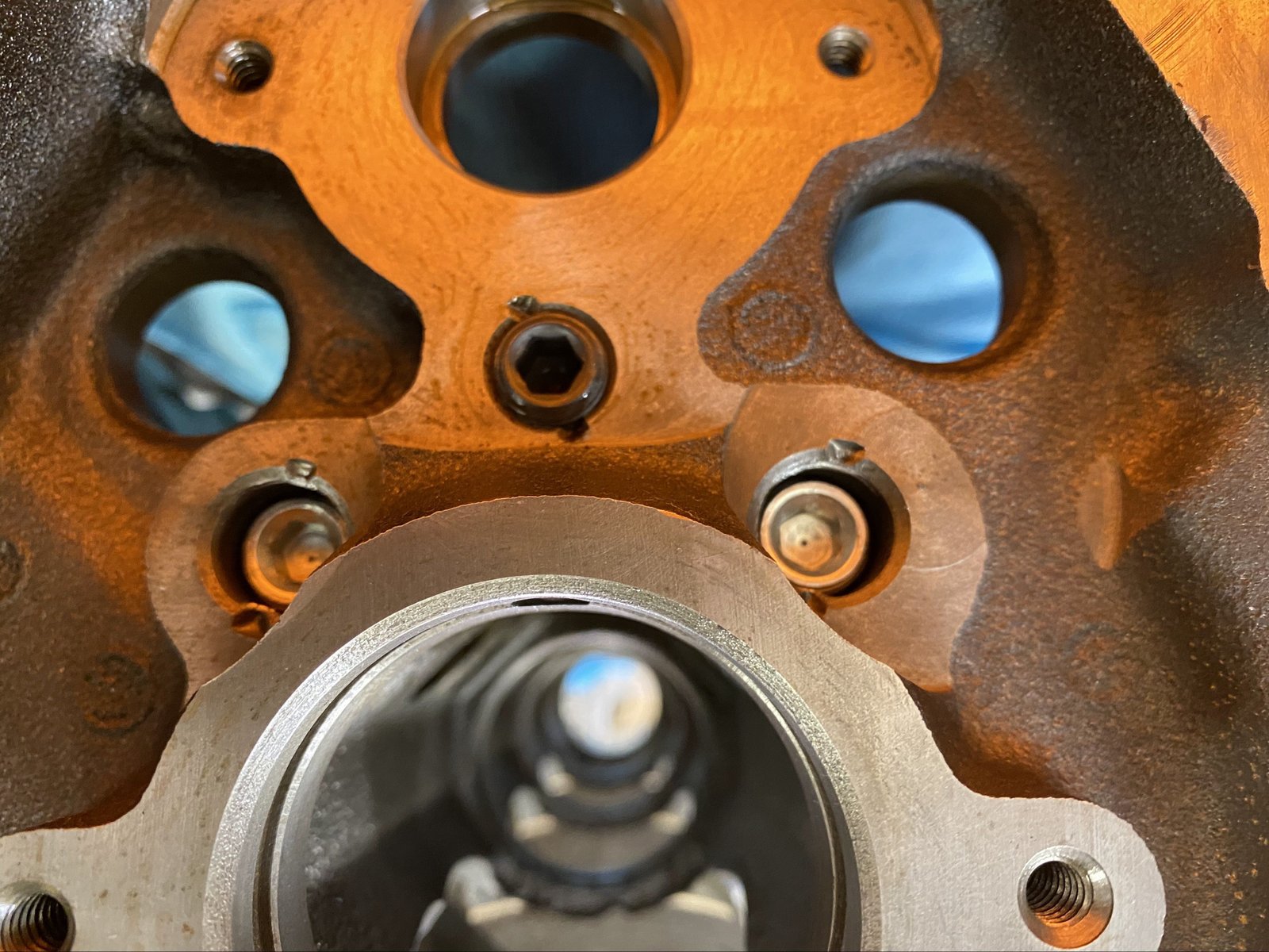
This is the steel ball that separates the oil fliter in and out
galley. I always take a photo of it as a verification that it
was installed.
And here are the front oil galley plugs. These are
threaded in place with oil on the threads...(not sealant).
I mark the cam bearings with sharpee as a visual aid to help me
with oil hole orientatin.
The #1 and #5 caps are Billet Speed Works which bought the
bankrupt company ProGram.
You can see the clearance written on the oil pan rail.
"24" means 0.024" and 0/0 means standard top and
standard bottom bearing shell. Using King XP bearings.
Pay attention to your camshaft when you get it. I made the
mistake of not looking at the camshaft when it arrived many months
ago. All too often Lunati will put the short pin in an LT1/LT4
camshaft. ---->
<-----and unless you have a pin-puller it will be a real pain
to swap the short pin for a long pin.
A few years ago I purchased a very high quality dowel pin puller
with this common mistake in mind.
And I purchased quite a few long pins to keep in stock although
this might be my last one.
And then later I noticed the camshaft is not drilled for the
1/2" opti-spark shaft. Lloyd Elliott was great to talk to
about this. He gave me his Lunati contact and we worked it out
that this is a proper sized cam core but just not for the LT1.
It will work though. I will have "Uncle-Randy"
machine the proper sized hole. For now I'll install the cam to
allow for rotating assembly mock-up. It is desirable to have the
camshaft and timing set installed to make sure the rods do not bump
into the camshaft. (this is a temporary timing set too...until
I receive the one I ordered yesterday).
Ring filing. I am very proud of the precision and squareness
(and no burrs). For up to 300hp nitrous I agonized over the
2nd ring gap spec. These are Total Seal rings and they spec
the 2nd ring same size as 1st ring. Mahle usually has the 2nd
ring tighter if running nitrous. I went with slightly tighter
2nd ring gap.
.030" 1st ring and .025" 2nd ring. The rings are
very far way from the piston top and that influenced my decision.
Top ring.
Top ring again.
Top ring in the bore.
Verified at .030"
2nd ring.
2nd ring to the right is at .025" gap. It is napier
style. The rings are also 4.032" out of the box as
opposed to 4.035". That makes them slightly lower
tension. I had been trying to order rings like that since
ERE#9 and Total Seal had discontinued the 4.032" ring.
Now Diamond is doing this almost by default and their influence with
Total Seal made these available again.
Notice how far down and away from the heat of combustion both the
1st and 2nd ring are on this custom Diamond piston.
Last view before installing rods/pistons.
Photo of rod bolts being torqued. The rod side clearance
is .018"
MLS head gaskets have arrived and now it is time to get busy with
the engine assembly. I'll start with rear main seal housing
and making sure it is centered.
.004" feeler at each of the 3 nubs. Then tighten the 4
bolts and it should be centered.
Then the Corvette seal goes in.
Titan gerotor oil pump. This is a revived company that took
over from Bob Saunders after the Ventura County fire.
The pump hit this larger main cap bolt and so I replaced it with a
smaller 12pt. I made sure the crank thrust was still the same.
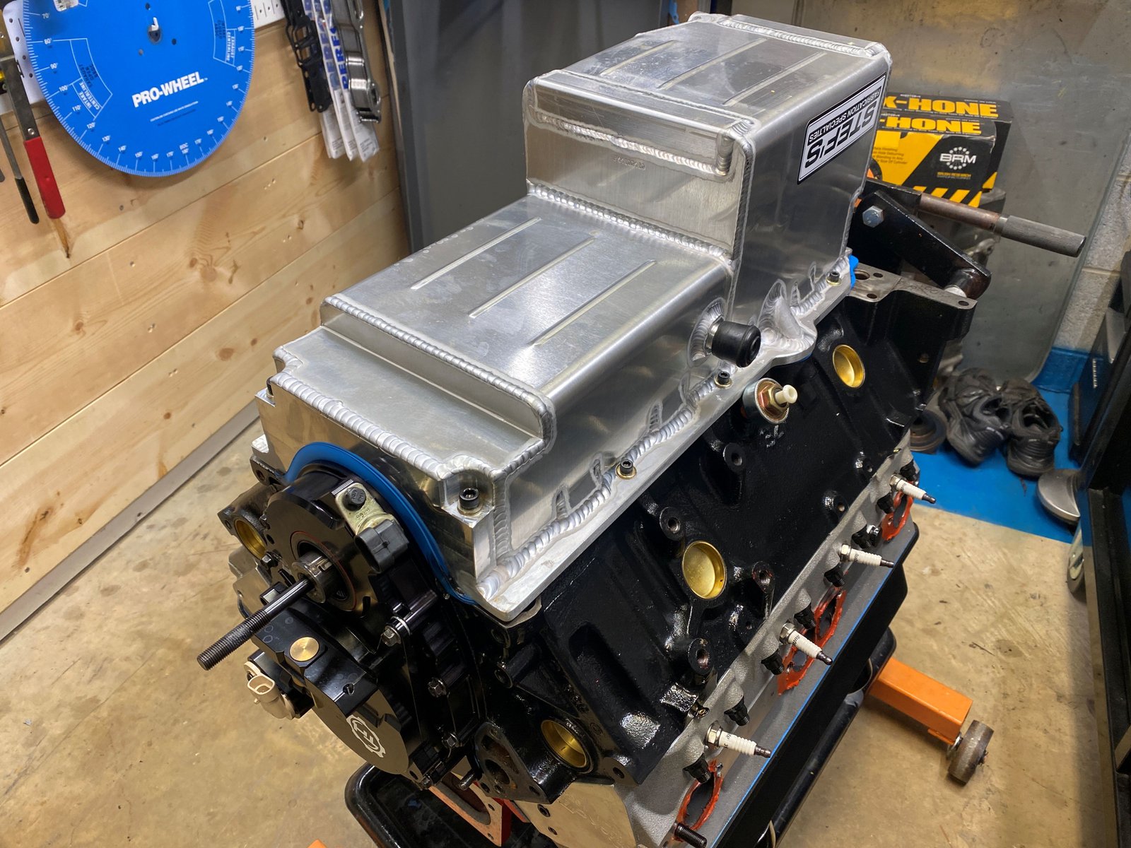
Pump test fit. It is massive. Only one pan will fit over
this...it is my own design from Stef's.
Test fit.
Crankshaft rear counterweight hits here. This spot always
needs extra clearance.
I have to be very careful with debris while working on the pan
fitment. See the aluminum dust on the crank.
This was the pan I had reserved originally for ERE92 but it had 2
oil pan drain fittings. The one at the bottom hits the Titan
pump.
Luckily I just re-stocked with 3 oil pans from Stef's. These
are built exactly as I need to fit the Titan pump. The oil
drain has to be on the passenger side and not the drivers
side. That pan to the left was a mistake by Stef's and it was
discounted to me. It will work with any other oil pump but not
the Titan.
Don't laugh at the windage tray. This stock tray is essential
to keep the oil from aerating. I messaged it to fit around the
big Titan pump.
Pan fits nicely.
Dip Stick seems to fit well.
Will the stick interfere with anything in the pan? It sounds
like it. I took a video with my DJI camera inside the pan and
it shows the stick hitting (just slightly) onto the flapper
support. I'll clearance that too.
The red pipe cap is for turbo oil drain back which will not be
needed for this engine but all of my Stef's pans will now come with
that fitting by default. The oil pan gasket is a shop test
gasket and the engine will have a brand new gasket right before it's
finished, (of course). The timing cover is only on
temporarily. The camshaft is at the machine shop getting the
1/2" hole drilled into the nose.
Now She is starting to look like
an ERE-395. Ready for ARP head studs and LE Cylinder
Heads. Before I do that I need to make sure the Crower
mechanical roller lifters are installed.
OK back to the camshaft. Now I have the proper sized hole
in the nose to receive the opti or the TorqHead sensor unit.
It's about 1/2" wide and 7/8" deep. Lunati had
skipped this step by mistake and sending it back would have cost a
bit of shipping money and time.
Here is "Uncle Randy's" pilot hole.
Now the 1/2" drill bit. The cam material is very hard
at least the 1st 1/4" or so.
Now the reamer.
Now a chamfer.
Here is the camshaft after the machine work. I'll be
changing the cam pin too. Actually I pulled the pin and turned
it around so that the un-molested end is sticking out.
The camshaft is on a reduced base circle. It is a
mechanical roller at 0.668" lift.
The cam pin is not sticking out too far and it's not too
short. It's just right.
I wanted to make sure that the TorqHead unit fits and it does
fit quite nicely.
After that TorqHead sensing unit mock up I removed it and also
removed the timing cover so that I could degree the camshaft.
Here is how I eye-ball the 0 deg. at T.D.C.
The camshaft took a few tires to dial it in. 1st it was
102 ICL with the timing set at zero. Then I installed the
crank sprocket for -4 deg (cam retard). That is because the
cam is supposed to be 104 deg ICL. The -4 deg position brought
the camshaft to 108 deg ICL. So I put it back to zero on the
crank sprocket and pushed the cam gear to the retard position while
tightening the camhshaft bolts. Then it was dead nuts on 104
ICL.
Crower lifters 66200TH-16
These are .300" taller for the LT1 block and did I say they are
mechanical roller?
While the lifters soak in oil I cleaned the ARP 12pt head studs
in the SafetyKleen.
Lifters installed before the cylinder head.
While I'm at it I can clay the piston tops to measure for piston
to valve clearance.
Lloyd Elliott TFS heads.
The heads are getting treated to Crower Shaft Rockers so the ARP
rocker studs will be removed.
Crower instructions. Looks like I shoot for .050" gap
with the checking too.
Here is is without any shims under the shaft rocker stand.
Here it is with .050" shims under the stand. It looks
good.
Here I am trying to level the checking tool so that you can see
the gap without the feeler installed.
Houston we have a minor problem. The pushrod holes in the
TFS heads so not allow the pushrod to engauge the shaft rocker cup.
(even a 5/16" pushrod was tested).
See here that the pushrod hole needs to be widened in the
inboard direction, (toward the intake manifold. Checking with
Crower for a solution and possibly the shafties may not be able to
be used.
Good news on the clay test.
.200" intake and exhaust.
Well....the obvious fix to be able
to run the shaft rockers is to have the pushrod holes
clearanced. These are the exact same head version TFS 195
which were on my Kent-Impala SS. The hole is at least
.200" wider inboard.
Uncle Randy just sent this photo to my
email. The full view of his Bridgeport vertical mill with
horizontal attachment.
Clinton Auto Machine has helped out
here by enlarging the pushrod holes as much as possible to hopefully
allow clearance for 3/8" pushrods. The intake pushrod
hole is way too close to the intake runner. We failed
conservative and did not "push" it into the intake
runner. If the 3/8" pushrod does not fit we will find a
thick walled 5/16" pushrod for the intake.
OK good news. The heads are home and the pushrod holes are
large enough for the 3/8" pushrods. Rocker tip witness
marks on the valve tip is dead-nuts-on.
Now I'm setting up the shaft rockers again. The .025"
shim set is what gave this perfect fit as per the Crower
instructions.
The pushrods touch the head gasket. Very slightly.
I'll figure something out to solve this.
It's the intake pushrod that is touching the Cometic MLS head
gasket.
This is the Stef's oil pan and I needed to add clearance for the dip
stick to pass. This looks rough but it's aluminum and so I
could not use tin snips. I made sure to buff the edges and get
rid of any sharp remnants that can fall off and into the oil pan.
The timing cover is on and the torque head sensing unit. Also
putting on the ATI-TorqHead hub after inserting the crank nose shim.
Stef's/Ellwein pan on.
ATI-TorqHead 24x hub on.
Now to fit the Titan gerotor oil pump shaft. It needs
trimming.
1st I buff down the O.D. here so that it can fit inside the stock
oil pump drive. Then I trim the bottom of the shaft as needed
to give about 3/8" of end-play to allow for expansion.
See here is the oil pump drive shaft and proof that it can set about
3/8" lower than the mounting boss. This is
important. You don't want this to bind and break.
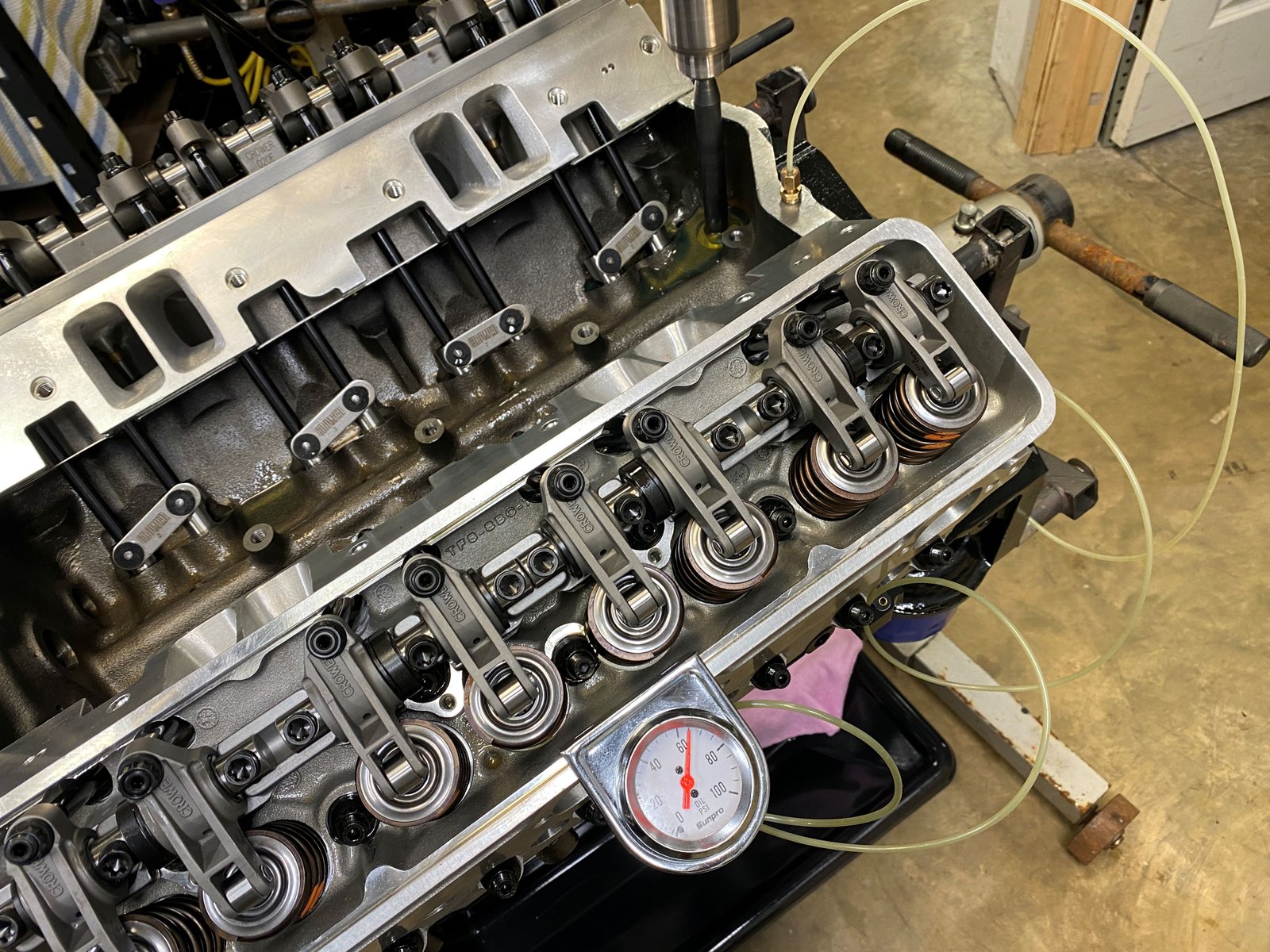
Oil pump spin test. 65psig. Exactly as ordered.
Oil passed up all of the pushrods. It took only about 2
minutes of drill spin. Next step is engine dyno.
This is the LT1 gasket for my carburetor intake manifold and it will
not fit obviously. I wanted to run the single plane Victor
Junior.
Here is the GM 777 gasket and it looks to be the one that Lloyd
Elliott used to gasket match.
The Victor Jr.
The LT4 ported by Lloyd Elliott. It fits quite well...(maybe
I'll set up an EFI system and run the LT4 manifold on the dyno????
Ended up aborting the dyno session. My 1st EFI wiring system
had weak coils and could not give proper spark when the engine was
under load. The engine was able to idle and take a slight load
and so it was not a total loss. The rings were able to be
seated. Found an oil pan leak too.
Turns out I did not put any RTV on the oil pan gasket. It
needs at least RTV at the front and back 1/2 moon.
Now all sealed up. Here is a photo of the Callies crankshaft
hub stud.