ERE-395 #93
4-Bolt Splayed cap 395 short block for twin turbo F-body.
Callies H-beam rods, Wiseco -32 dish blower pistons
Callies Dragonslayer crankshaft
Callies will be balancing (re-balance) the crankshaft that was
supplied by the owner of this engine project.
I'm collecting weights in order to provide this info to Callies.
Wiseco blower pistons with the S718 wrist pin. Also Swain
Tech thermal coating on the piston top.
The rings are Total Seal CSL3690-35
Here is the crankshaft being prepared for shipment to Callies.
The block has been at the main cap machine shop for quite a
while. The guy who does the work is worth waiting on.
Here is the core that I selected. A 2-bolt LT1 block.
The block will have the bores sonic checked for adequate wall
thickness in addition to the standard machining process.
Block has returned from the machine shop with main caps
fitted. Also partial water jacket fill to just under the
freeze plugs.
Crankshaft has been balanced to 1751g by Callies
ProGram main caps.
A work in progress. I've been improving my shop assembly
area for ergonomics.
Callies H-beam rods and King CR807XPN bearings. Most area
at .0025" clearance with a few at .0023".
...A good way to keep things organized especially with the
Left-Right pistons.
Ring filing. I went with .030" gap for 1st ring and
.030" gap for 2nd ring.
Top ring is steel and Total Seal has no marking for
"UP". You have to see the tiny bevel on the ring and
have that facing up. I marked them all with an X for up.
Rings installed and pistons in order, (and cleaned with the
parts washer one more time).
Photo to document the partial block fill. This epoxy style
fill is to the freeze plugs. An unfilled block is about
5" from deck to bottom of water jacket. Here the deck to
fill surface is 3.5 to 4", (and so the fill is from 1 to
1.5" thick)
The fill will cause the oil temperature to be higher but
generally the water temperature will remain the same. Most
cars run with oil temperature too cold to begin with, especially
strip cars. (with the exception of road track cars). If
you run E85 the water temps will be even cooler. The block
fill will help stabilize the bores under high boost.
Beginning to measure the mains for bearing fitment.
Crankshaft set in place to check for stroker clearance.
All pistons/rods installed. This gives me a pre-check for
a few things. One is piston to deck height, (looking like
.010" in the hole). This usually changes a tiny bit after
final assembly and torque. Second is rod to block
clearance. I found 2 spots that I will be required to grind
more. This photo is just showing top dead center.
Next step is to disassemble completely, grind the block, clean
the block, install cam bearings, reassemble rotating assembly with
camshaft and timing set installed.
Here is where the block gets a bit of relief to allow for oil
drain back at the drivers side front of the cylinder head.
The block gets all of the external sharp casting flash smoothed
off.
Touch up paint via POR15 engine black
The block was clearanced at 2 areas for additional rod to block
clearance. Then hot water pressure washed. Then air
dried and oiled with WD40. Then touch up paint.
I like to thread and tap the front oil gallies. I use a
vented plug at the lifter gallies for timing chain cooling.
Premium Durabond camshaft bearings going in.
Tony Mamo spec camshaft. Nice billet core.
231/235/115 duration at .050"
.595"/.595" lift with 1.6 rockers.
Thrust is .005"
Timing set provided by engine owner. This has a few miles
of use from it's previous engine. Using the EFI Connection 24x
cam and crank system. I make sure to loctite the camshaft
bolts and make sure the camshaft dowel pin is shortened so as not to
drive into the camshaft sensor.
This one Connecting rod needed a bit more clearance at #6
hole. The rod shoulder on the Compstar rod is already very
well clearanced/profiled but it needed just a little more.
Rod side clearance at .020"
Rod bolts are at 75ft-lb.
ARP and Milodon main studs at 80ft-lb with ARP thread lube and
oil. The outer bolts are at 60ft-lb.
Here is the EFI Connection camshaft sensor holder and it shows
the typical too long of a camshaft pin, (from previous motor).
I always check this and have seen almost every camshaft with too
long of a pin. They all have to be shortened when using this system
and sometimes with the TorqHead.
All buttoned up.
Final check of piston to deck height. .008"
In-The-Hole.
Reusing the previous engine's lifters. These are LS7 I
believe.
I'm using a GMPP lifter guide that mimics the LS lifter
guide. If you want to change the camshaft in the future you
won't need to remove the intake manifold. Just turn the crank
2 rotations and all the lifters stay up in this guide.
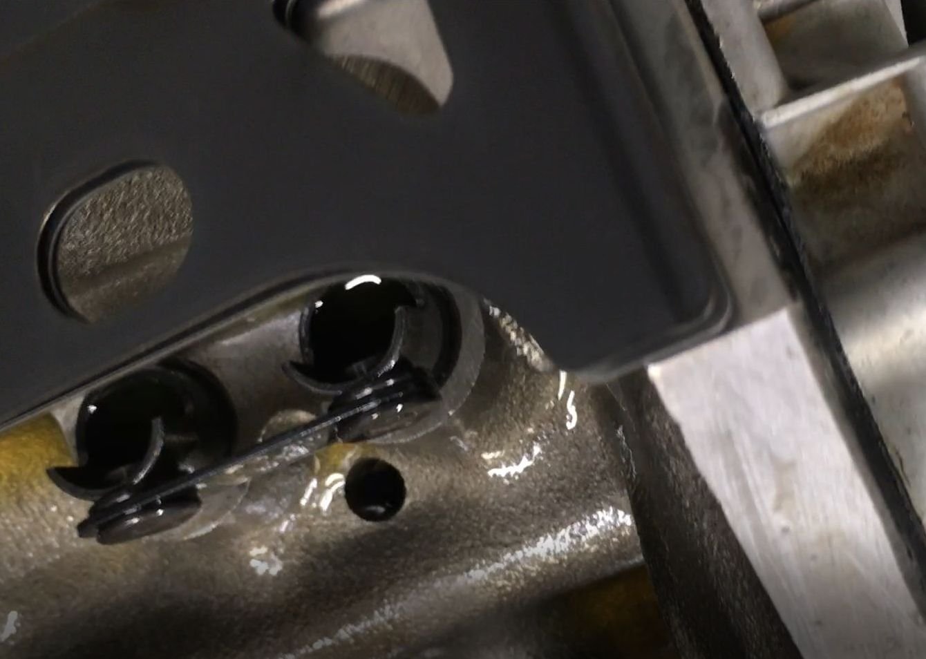
Orphan photo that shows the main oil galley plug installed under
the rear main cap. (this photo is from a cell phone
boroscope-endoscope).
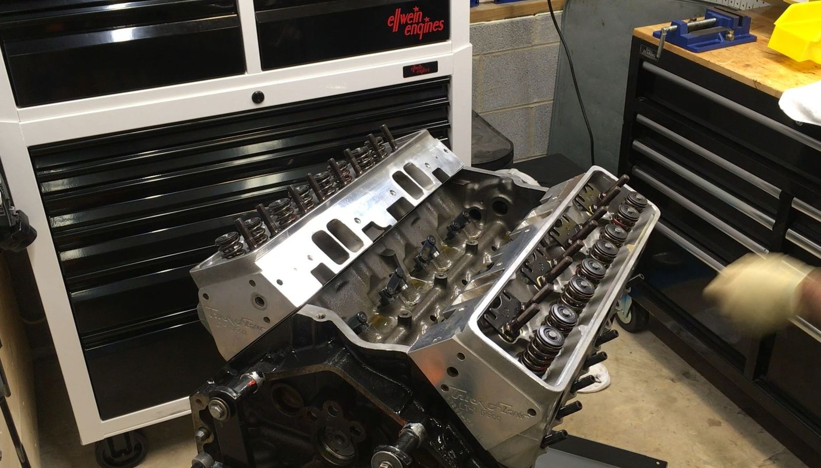
Heads on. The next set of photos are actually video screen
captures (forgot to take photos while doing a YouTube video).
Unboxing of Crower 66310LM-16 hydraulic lifters.
Johnson brand and Crower brand. Which is the true maker?
I don't know.
Lube up with oil prior to installation. These type of
lifters must be installed before the heads go on.
Sorry out of sequence. Heads on and ready for torque.
ARP head studs at 80 ft-lb
Cleaning out the head bolt holes prior to stud installation.
Front left of block requires a bit of clearancing for the
Cometic head gasket. This is for oil drain back from the
heads. I do this for every engine no matter.
Refurbished TFS heads ready for installation. 62.5 cc
chanbers
ARP 12pt nut head studs get cleaned in the parts washer and
further cleaned with acetone. The RTV on the threads for water
sealing.
80 ft-lb torque spec.
Let's get things ready for the dyno session and button her up. I need
to set the engine on the ground to get to the rear main seal area.
Here is everything needed to install the rear main seal and its
housing. The gasket, the used housing which has been cleaned up, 3 feeler
gauges (.004") and RTV.
I set the .004" feeler gauges at each of the 3 alignment tabs.
Then tighten up the bolts and install the Corvette seal.
One last look at the camshaft prior to installing the cam core plug.
I did not install the windage tray or the dipstick (yet). 1st thing I
want to do is install the oil pan without RTV and bolt it down firmly to see if
there are any clearance issues.
All good.
Let's install the ATI hub and damper.
The hub needed to be honed to get the interference fit down from the
as-found of .005" to a reasonable .002"
I make sure the hub is seated well against any reluctor that may be
installed.
Here I'm using a stud and numerous washers to press the hub (with damper)
on.
Then installed and torqued the ARP crankshaft bolt.
She's looking good. (Remember I still have to remove the oil pan and install
the windage tray and do the dipstick tube modification to allow it to fit
over the main caps.
But for now I'll make sure I have TDC set with my bendable dyno timing
pointer.
I also like to mark 35 deg to give my eye an easy mark to see during the
dyno testing.
Here I am attempting to tackle the addition of the stock windage tray and
the installation of the Lokar dipstick and tube.
The tube must be shortened otherwise it will bump into the larger-than-stock
main cap. The "stick" then is not guided as well and it
"might" take a bad path and bend into the path of the rods and crank.
One thing that helps keep the oil dip stick on the correct path is to cut
away some of the windage tray. That prevents the stick from hitting the
tray and bending to the front or rear and into the path of the rods.
Having a longer tube helps too but the Lokar is so much different than stock
that I could not keep any length of tube. Not one bit of tube could be
saved to help guide the stick.. The Lokar stick has a relatively large bulbous
end that won't bend and so the guiding tube has to be cut back far enough to let
the stick (with the thick and stiff bulb) pass by the main cap. Well, so
anyway the dip stick will slide past the main cap and not hit the windage tray,
nor will it bend forward or aft and hit the rods...that is if you insert it
properly indexed, (I have an index mark on the stick).
And to the windage tray topic....I removed the stock windage tray because it
interfered with the oil pan. Now here in this photo I show the blue
loctite that I added to the PCV oil baffle inside the valve cover.
Oil pan on, (just relying on the oil pan built-in windage mechanism).
Also have the valve covers on and they fit very nicely. I think this photo
has the dyno intake manifold just sitting on without the gasket...for the photo.
And the dyno water pump is on. This is an HD version of the Meziere.
Another pose. GMPP dual plane carburetor manifold is on but not bolted
or gasketed.
Now for the oil system "test". 5 quarts of oil and electric
drill spinning the pump and I had 65psig of oil pressure and the
lifters/pushrods/rockers filled with oil in about 5 minutes.
Now the dyno manifold is RTV'ed and gasketed and bolted on.
And the dyno distributor is installed and timing set by eyeball to 35* BTDC
with #1 piston at the compression stroke.
One day I'll make a video of this process. I tried here but failed in
the camera framing and technique.
Overall total fail on the videography...but I did remember to take photos.
Now we will take a time-out and patiently wait for a dyno session.
Very nicely powder coated intake manifold. Provided by the customer.
I washed it in the parts washer but I should remove the oil tray to check for
gunk.
Looks like a little bit in here. But no. This is cooked on and
it is not loose debris. Fooled me.
One last view of the nice Johnson/Crower lifters.
Oil pump drive gear installed at torqued to 20ft-lb and intake manifold gaskets
installed.
Now wrapping and protecting for the shipping. I failed to get a photo of
the nice gloss black intake manifold.