Starting off much like every other engine project and that is with
the crankshaft balance calculation.
It all added up to 1710 grams for the bob-weight. The Eagle
crankshaft will now be balanced to that value and while it's at
the balance shop it will have the rod and main journals
polished. Even a brand new Eagle crank can benefit from a
polish.
Big time delay on starting this project. I have all the
parts but was finishing up ERE92 and ERE93. Here is the block
after machine shop work of bore/hone/deckplate finish hone/install
main caps.
Today's job is to check that the block has enough clearance for
the stroker crank/rods. I had the machine shop
pre-clearance. I'll mock up the entire rotating assembly and
mark any spot that needs more grinding.
The block will need a final wash and grind of sharp edges and
painting.
#1 piston/rod combo has good clearance.
Here is a nice close up of the Wiseco -32cc dished forced
induction piston.
A good day today. All of the rods will clear the block
without additional grinding. Next step is to remove
piston/rods and grind the sharp casting areas of the block and clean
it an make it ready for paint.
I figured I would snap a photo of #1 piston at TDC while it was
here.
Storing the piston/rod assemblies while I work on the
block. I also tap the front oil galleries for threaded
plugs. That alone will cause me to have to wash the block.
Photo not shown...but the block was
cleaned up and it will be ready for paint tomorrow.
Love this paint. I believe it is stronger that
POR-15. It is certainly more expensive than POR-15.
I painted outdoors and just rolled it in for the nice indoor
climate for drying. See my Pandora ZZ-TOP channel playing in
the background.
OK, the block is cleaned and painted. Let's get to work on
assembly. Cam bearings installed. Durabond CHP8.
Photo of the rear of the camshaft for future reference.
It has the proper longer LT1/LT4 pin and also the 1/2"
pilot hole for the opti or TorqHead.
Camshaft in background cleaned and ready for installation.
Cam core plug installed.
Now the cam is installed.
Every motor gets a photo of the rear main cap oil galley
plug. This is more for my records than anything else. If
I don't see this photo then I don't know that I put this plug in.
Main bearings are a mix of "x" and standard sized King
HPX (the best of the best). Clearance is from .0025 to
.0030"
More tomorrow.
Thrust initially too tight. Sometimes the bearings need to be
massaged with scotch bright to get more clearance.
Now she's at .005"
Well dang. I ran into something weird that I cannot explain as
of this typing. After measuring for main clearance the day
before I then put the crank in and torqued the mains. The
crank felt a bit tight, (not binding but just did not spin
freely). I decided to plastigauge and found #4 main too
tight. .0015" and I double checked bore gauge and it
still showed .0025"
Why so different I don't know even now. Also all the other
mains showed .0020" on the plasti gauge and .0025" via
bore gauge.
Here is my plastigauge check.
I re-measured the mains with the bore gauge and plastigauge and #4
went to x/x (.001" over on each bearing 1/2 shell). All
the mains are X for both 1/2 shells except #1 which is standard
size. So in the photo above the top numbers are with bore
gauge and the bottom numbers are plasti-gauge. The most important
part is that the crank spins very nicely as it should. The #4
being too tight may have lead to a spun main if I had not added the
"feel" or gut feel check to the building process.
Degree check came out to 105 deg intake centerline on a 106 deg cam
card. As close as I can get to perfect. One thing about
being a tad advanced is that as the timing set stretches then cam
timing will retard (back to 106).
Piston is in the hole ?" I forgot the number and it's
written down in the folder in the shop.
Nice timing set. The Cloyes extreme duty.
Ring filing of the Total Seal steel 1st ring. Mild boost up to
15psi gap is .023 to .024"
2nd ring is same gap as 1st ring according to Total Seal.
I wanted to show how nice a job my Goodson ring filer does.
This nice clean cut is very hard to get. It really takes a
good tool and careful technique. This is the Napier 2nd ring.
Compstar rods getting torqued to 75ft-lb which gives the proper
stretch. Here is .0055"
All the rod bearings came out to .0020" to .0022"
clearance with King XP standard size.
Here I am installing the pistons
All 8 pistons installed.
All 8 rods torqued and checked for .005" rod bolt stretch.
Here is a new way that I'm measuring for piston-to-deck
height. Since the piston rocks in the bore I am taking an
average (at the piston center-line). I made sure the piston
was at top of bore then zeroed the gauge at the block deck.
Then measured this spot..
Then this spot...and take the average of the 2 for a -.015"
IN the hole. I don't deck the blocks any more than
needed and most of the time the piston is in the hole. I'll be
ordering a .027" MLS Cometic head gasket set and so the piston
to head will be .042"
By not decking more than needed the intake manifold will fit
much better.
Crower lifters need to be soaked in
motor oil prior in installation.
Here is a new rear main seal housing with the premium
seal. I have .003" feeler gauges at the 3 alignment nubs
to validate that the housing is centered.
Then I measured one chamber of each head to get a record of the
combustion chamber volume. This one is 53cc.
This one is 52cc.
Static compression ratio calculation:
52cc combustion chamber
5.9cc gasket
-32cc piston
-0.015" in-the-hole
3.875" stroke
4.030" bore
9.7:1 static compression ratio
Time to clean the packing oil off of the head stud threads
This photo is taken just after the SafetyKleen washing.
I put in the hydraulic lifters prior to installing the heads
just in case they won't fit with the heads on. I know that
these stock style crower lifters can be installed with the heads on
but it's a good habit to stick to just in case.
Cometic MLS head gaskets. This is a .027" compressed
thickness and with the pistons about 0.015 in the hole that gives
0.042" piston to head clearance. I aim for 0.035"
but in this case I would not want the gasket to be any thinner than
this.
Heads on
Torqued to 80ft-lb
Checking for pushrod length. Typically stock heads and
stock style lifters want 7.20 to 7.30" and you could just put
an actual 7.20" pushrod in and test it but why not use a fun
tool when you have it.
This measured out to be 7.125" but don't forget to factor
in that you need some lifter "pre-load" So I added
0.050" which rounds close enough to 7.20...."try a
7.20" pushrod"...is what the tool is saying to me.
Manley 7.200" pushrod leaves a very nice witness mark.
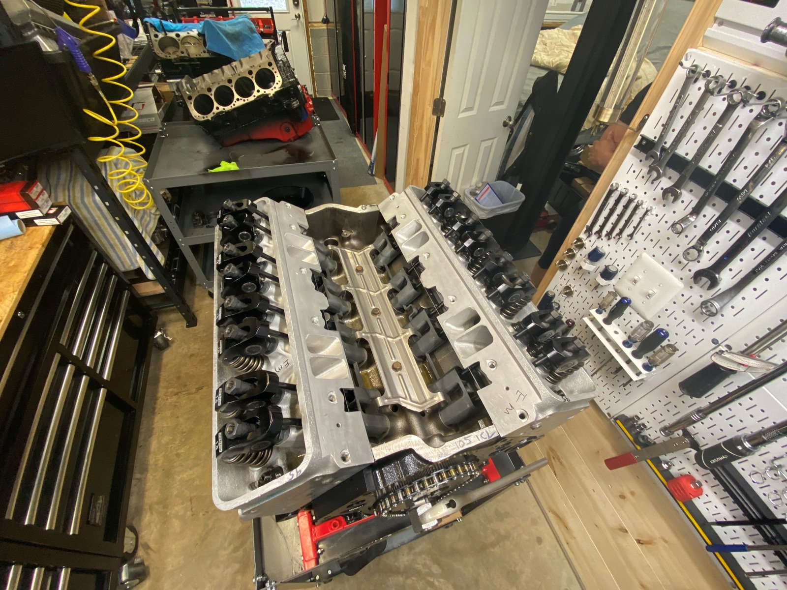
The Lunati 1.6 rockers and very nice. They were supplied
by the customer. I have never used this particular rocker in
an engine but I like them. They look like a sturdy
design. These are "self-aligning"
I like my small (on-purpose) engine building area.
Notice the GMPP lifter guide I use instead of dog bones.
These are LS style which will allow for a camshaft change without
removing the intake manifold. They are very reasonably priced
too. Cheaper than dog bones. GMPP 88958652 $17 each.
Time to tackle the finding of and washing of a timing cover
core.
Cleaned up on the outside....
...and inside.
New seals and a Kennedy 1/2 $
Putting the TorqHead hub on. I stopped just in time
because the sensing unit is difficult to install with the hub
on. The hub 24x reluctor gets in the way...And so I pulled the
hub off, (it was on only 1/2 way).
And then I remembered to put in the spacer ring which takes the
place of a stock reluctor. If you don't have a 1996 with a
stock 4x reluctor then this ring will be used to take up the space
of the stock 4x reluctor. That gives better pulley belt
alignment.
Notice that nice Callies crankshaft stud. I use these
whenever I have them in stock. They make for a good way to
install the crank hub and they give good clamping to the hub and
replace the crank bolt.
Sensor alignment tool.
Shim of the crank sensor. It only needed 1 shim but it may
take 3 or 4 shims. You always have to measure.
Cleaned up this used set of Corvette composite valve
covers. The previous owner must have used conventional oil
because they were brown inside.
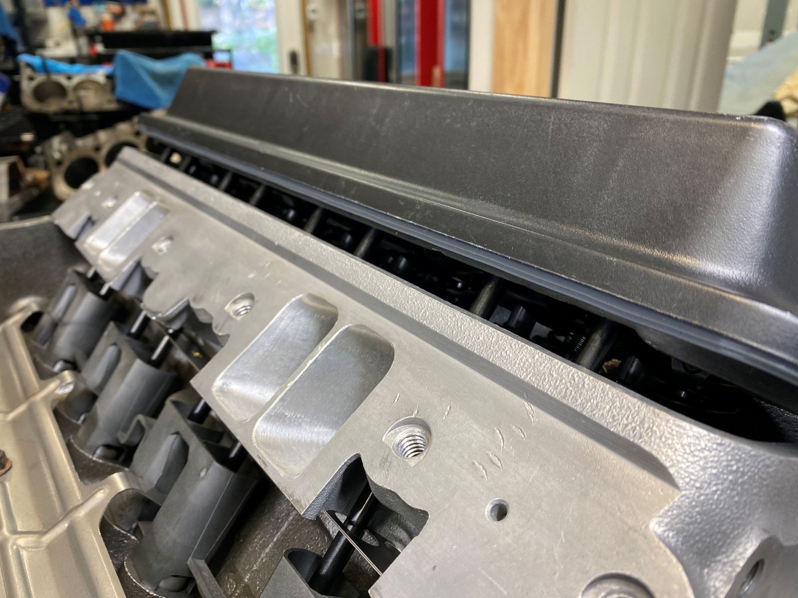
Turns out that these nubs must be removed in order to clear the
rockers. Not a very difficult procedure. You just take
vice grips and break them off or grind them off.
That work will be for tomorrow.
Today's work.
The damper is a Powerbond PBBPB1481-SS
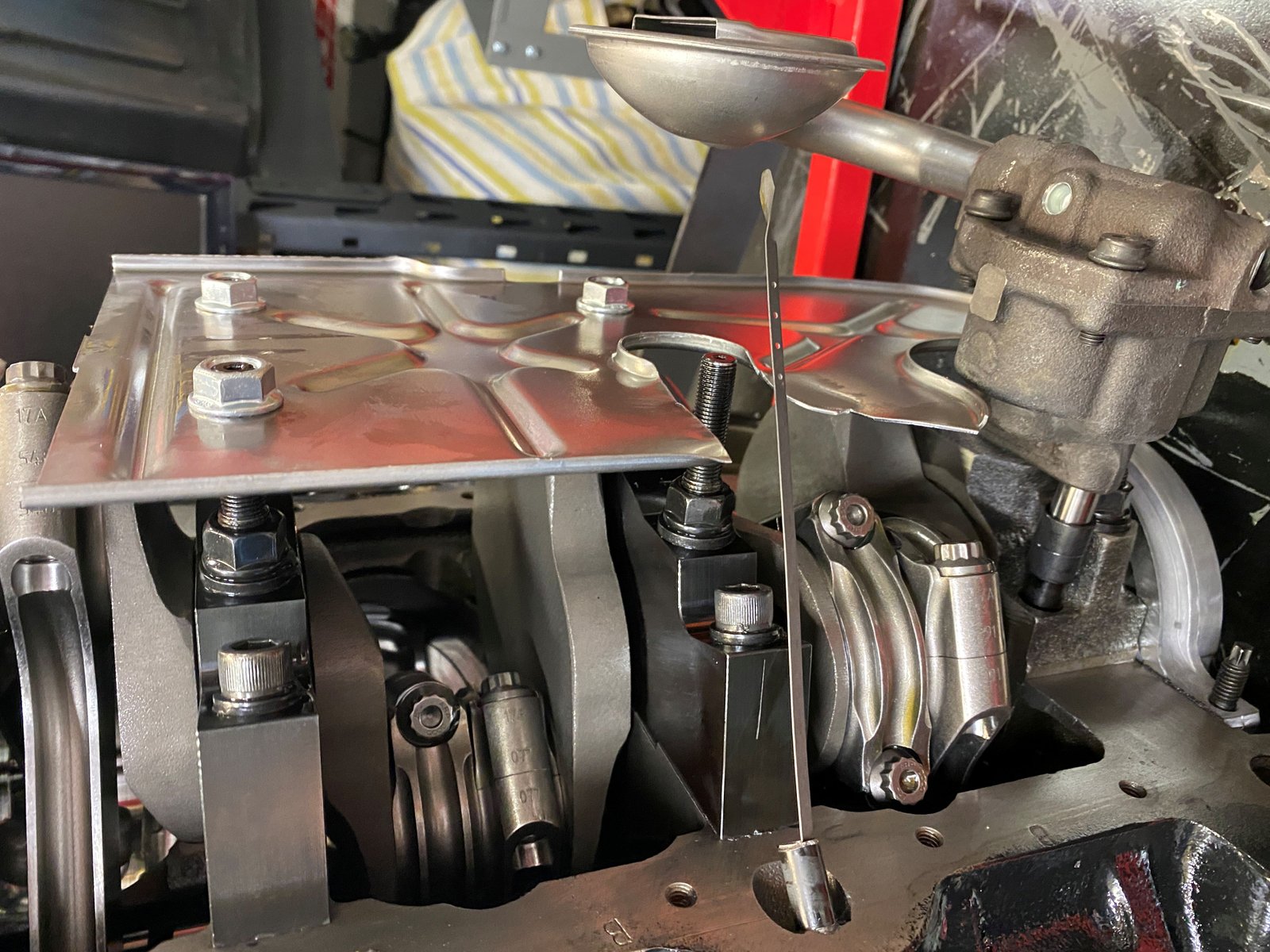
Making room for the dipstick. Here I have cut the windage
tray to allow the stick to pass into the oil without being diverted
into the path of the crankshaft.
And here is a close up of the rod clearance to the windage
tray. This tray always needs to be massaged in order to allow
the rods to clear...especially the 3.875" strokers.
Here I marked my target timing for the dyno...36*
BTDC.
Now trying to get the Corvette valve covers to fit. I just
needed to grind off the nubs shown here.
Dyno intake manifold is on.
Notice I do not have the customer's Corvette valve covers on the
engine. I was not able to find an oil filler cap to fit the
passenger side valve cover. Also could not find a grommet for
the PCV hole. Those are not all too common (at least here in
my shelf stock).
Ready for the dyno.
Now for an update.
At the dyno I suspected that the intake manifold gasket seal failed
and allowed oil to be sucked out of the valley and into the
chambers. The exhaust pipes were oil smoky at idle. The
heads are highly modified and no matter what intake manifold I use
they fit poorly. But I do believe that a good application of
Right Stuff RTV at the gasket ports will make for a good
seal. I'm going to try that out and run the engine on my
new test stand. If it runs well then I can ship with a
certified good intake manifold seal. If it runs poorly then I
need to investigate further.
Below are photos of the stand prior to assembly of the fuel system
and EFI wiring.
This is quite an undertaking. But the days spent making a
good EFI harness will pay off big time at the chassis dyno. I
spent time making fuel line connections and hoses and terminating
electrical connections. I found 3 used fuel rails and made one
good fuel rail out of the 3. I bought a brand new stock fuel
pressure regulator. Lots to do.
Still to-do....make spark plug wires for the coil packs, make a
water pump electrical connection, terminate the battery cables with
good lug crimps, wait for a few more parts such as 10mm to 6AN fuel
pump adapters and radiator hose adapters. Most everything was
provided by Summit for this engine run stand but not exactly
everything. Still a very complete kit. I'll tune the
engine with the tune from my car and change the fuel injectors to
30lb/hr. I have an exhaust system to add when it's time to run
the engine. More to come.......
Making good progress on the wiring. This is a Painless brand
harness for F-body. I tried to communicate with my PCM and it
failed. Looked in the instructions and it mentioned adding a
wire to the ALDL position #2 and #7 Blue PCM connection (don't quote
me I'm going by memory). The "additional serial data
connection". Once I did that then I could communicate
with the PCM. HP Tuners for the win.
Now while I wait for the fuel line fittings to arrive from Summit I
can finish off a few things. Here I have the spark plug wires
terminated. It is looking more and more complete.
The engine ran quite fine on my test stand. All good.
The water hose mishap was lesson to me to double check
everything. Now it is time to ship.